Goodrive300-01A series VFD for air compressor Wiring instruction
-9-
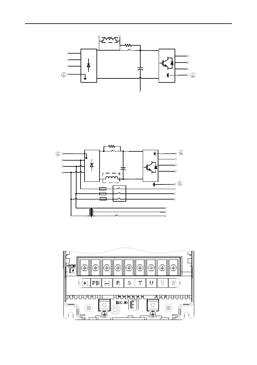
Figure 3-4 132–200kW main circuit wiring diagram
Note:
1. Optional external DC reactor for 132–200kW.
2. See Appendix B for filter and reactor model selection.
3.1.2 Main circuit wiring diagram of single-VFD integrated machine
R
S
T
U1
V1
W1
U2
V2
W2
220V/TAH
0V/TC
Master
Fan
Solenoid
valve
Figure 3-5 Main circuit wiring diagram for 7.5–15kW single-VFD integrated machine
Note: Optional built-in DC reactor for 7.5–11kW.
3.1.3 Main circuit terminal diagram of single VFD
Figure 3-6 7.5kW main circuit terminal diagram
 Loading...


