Goodrive300-01A series VFD for air compressor Commissioning instruction
-18-
4 Commissioning instruction
4.1 Commissioning instruction for the dual-VFD air compressor
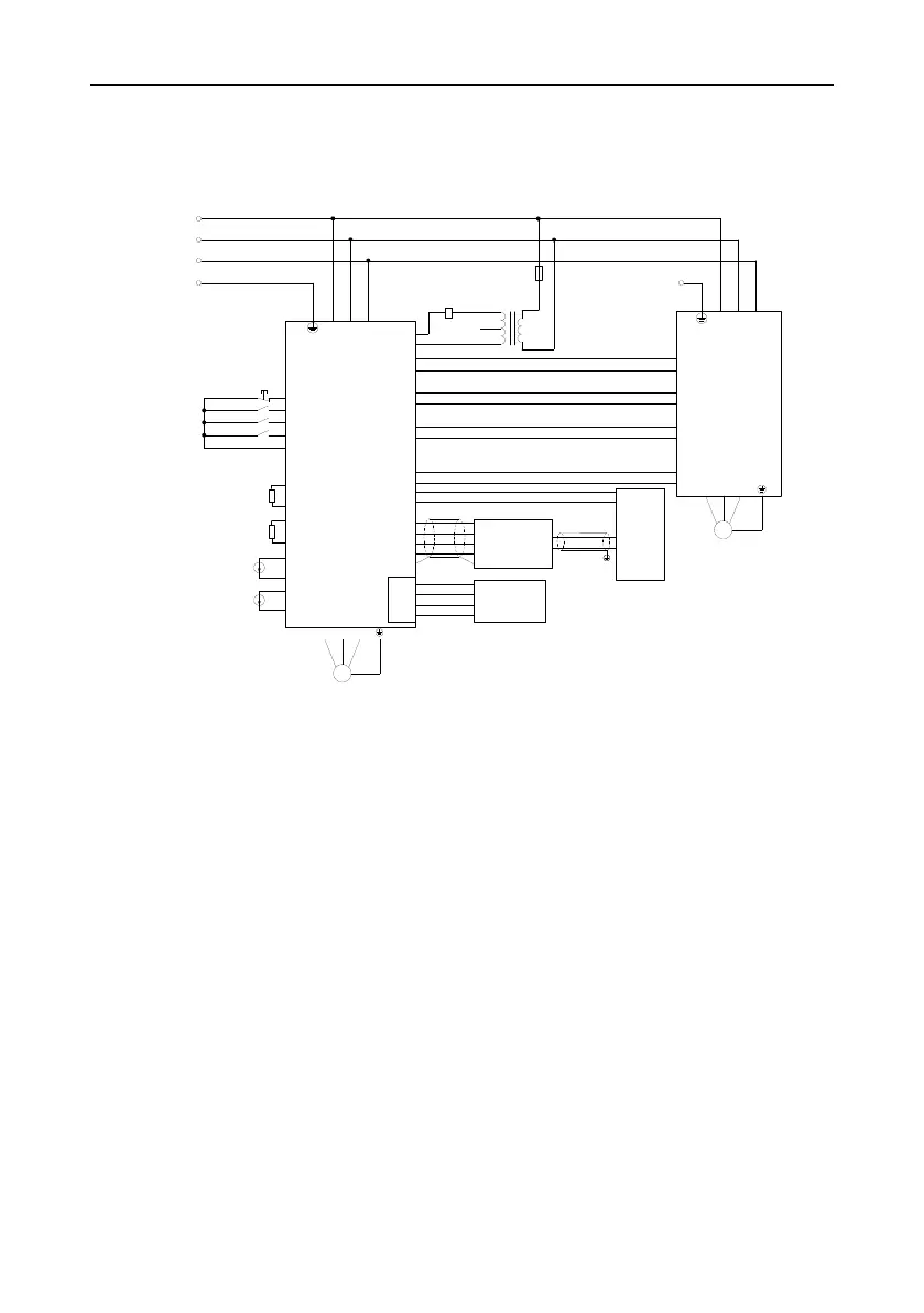
4.1.1 Wiring diagram of the dual-VFD air compressor system
R
S
T
Master VFD
R
S
T
GD300-01A
PE
COM
COM
S5
S4
S3
S1
Emergency stop
PTB1
PTA1
P1-
P1+
P2-
P2+
RO1A
RO1C
RO2C
RO2A
Solenoid coil
220V
110V
0V
R
S
Low-frequency
transformer
A01
GND
Power detection
module
PT100
Discharge pressure
Auxiliary pressure
PTB2
PTA2
PT100
Oil gas temperature
Auxiliary temperature
485+
485-
GND
+24V
CGND/PE
485+
485-
GND
+24V
485+
485-
GND
+24V
M
Cooling fan
COM
S1
AI2
GND
GD100/GD10
V WU
R
S
T
M
Main motor
V WU
PE
Cooling fan
start/stop signal
Analog
output
Fan fault
CN10
Wireless data
collection terminal
COM
S2
RO1A
RO1C
485+
485-
Fan VFD
485-
485+
HMI
Figure 4-1 Wiring diagram of dual-VFD air compressor system
4.1.2 Commissioning steps for the dual-VFD air compressor
It is recommended to use touch screen for display and commissioning, and the commissioning steps
are shown below (if the controller used is made by other manufacturers, contact our technician for
details).
1. Perform wiring according to Figure 4.1 and ensure that the VFD for air compressor and the
housing of the air compressor are grounded properly.
2. After power up, the following page is displayed on the HMI.
 Loading...


