Goodrive300-01A series VFD for air compressor Commissioning instruction
-27-
4.3 Commissioning guidance for single-VFD integrated machine
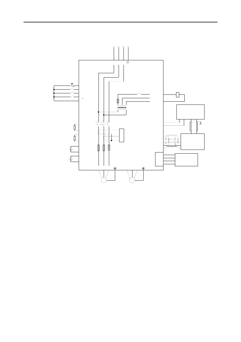
4.3.1 Wiring diagram for single-VFD integrated machine
Power
detection
module
485+
485-
GND
+24V
CN10
485+
485-
GND
+24V
CGND/PE
485-
GND
+24V
485+
U2 V2 W2
M
COM
COM
S5
S4
S3
S1
Emergency stop
PTB1
PTA1
P1-
P1+
P2-
P2+
PT100
Discharge pressure
Auxiliary pressure
PTB2
PTA2
PT100
Oil gas temperature
Auxiliary temperature
Cooling fan
S2
COM
R
S
T
PE
R
S
R
S
T
U1 V1 W1
M
Main motor
220V/TAH
0V/TC
Solenoid coil
GD300-01A VFD
integrated machine
7.5-11kW
0V
220V
110V
CN11
485-
485+
HMI
Wireless data
collection terminal
110V/TAL
RO1
Figure 4-18 Wiring diagram for single-VFD integrated machine system
Note:
1. RO1 port of single-VFD integrated machine is connected to solenoid valve coil port by default
before delivery. If the touch screen used are made by other manufactures other than INVT,
please set RO1 to solenoid valve control (P06.03=28).
2. Refer to 4.2.2 Commissioning guidance for single-VFD air compressor for the commissioning
guidance of single-VFD integrated machine.
 Loading...


