Goodrive300-01A series VFD for air compressor Commissioning instruction
-25-
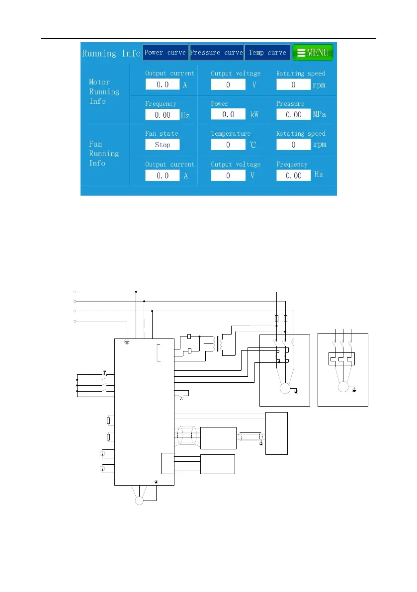
Figure 4-14 Running information interface
10. After adjusting user parameter, factory parameter and maintenance parameter according to the
touch screen manual, return to “workspace” interface and click “start” to run.
Note: All the parameters displayed in the interfaces in “4.1.2 Commissioning steps for dual-VFD air
compressor” are for reference only and subject to actual displayed content.
4.2 Commissioning guidance for single-VFD air compressor
4.2.1 Wiring diagram for single-VFD air compressor system
R
S
T
Master VFD
U V W
M
R
S
T
GD300-01A
PE
COM
COM
S5
S4
S3
S1
Emergency stop
PTB1
PTA1
P1-
P1+
P2-
P2+
RO1A
RO1C
RO2A
RO2C
Solenoid coil
220V
110V
0V
R
S
Low-frequency
transformer
M
Cooling fan
Adopt thermal relay to protect motor
overload
This is the backup plan
PT100
Discharge pressure
Auxiliary pressure
Contactor coil
Ib
Ic
Ia
PTB2
PTA2
PT100
Motor overtemperature
Oil gas temperature
Auxiliary temperature
M
Cooling fan
Adopt current transformer to
protect motor overload
KM
KM
S2
COM
FR
FR
Power detection
module
485+
485-
GND
+24V
CN10
485+
485-
GND
+24V
CGND/PE
485-
GND
+24V
485+
KM
Fan fault
Main motor
485-
485+
HMI
Wireless data
collection terminal
Figure 4-15 Wiring diagram for single-VFD air compressor system
Note: Pay attention to the dotted terminals during installing and wiring the current transformer,
 Loading...


