Goodrive300-01A series VFD for air compressor Wiring instruction
-8-
3 Wiring instruction
3.1 Main circuit wiring and terminal description
3.1.1 Main circuit wiring diagram of single VFD
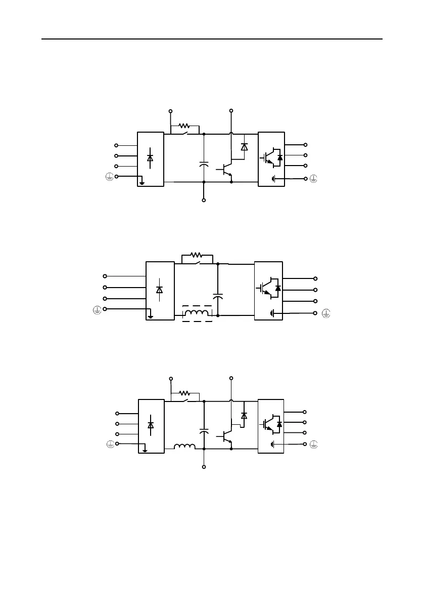
Figure 3-1 7.5kW main circuit wiring diagram
Note: There is brake circuit but no DC reactor for 7.5kW
Figure 3-2 11–15kW main circuit wiring diagram
Note: There is optional built-in DC reactor for 11kW and standard built-in DC reactor for 15kW.
Figure 3-3 18.5–110kW main circuit wiring diagram
Note: There is internal brake circuit for 18.5–22kW; there is no internal brake circuit for 30–110kW;
there is standard internal DC reactor for 18.5–110kW.
 Loading...


