INVT SV-DA200 AC Servo Drive PROFINET Technical Guide V2.63
21
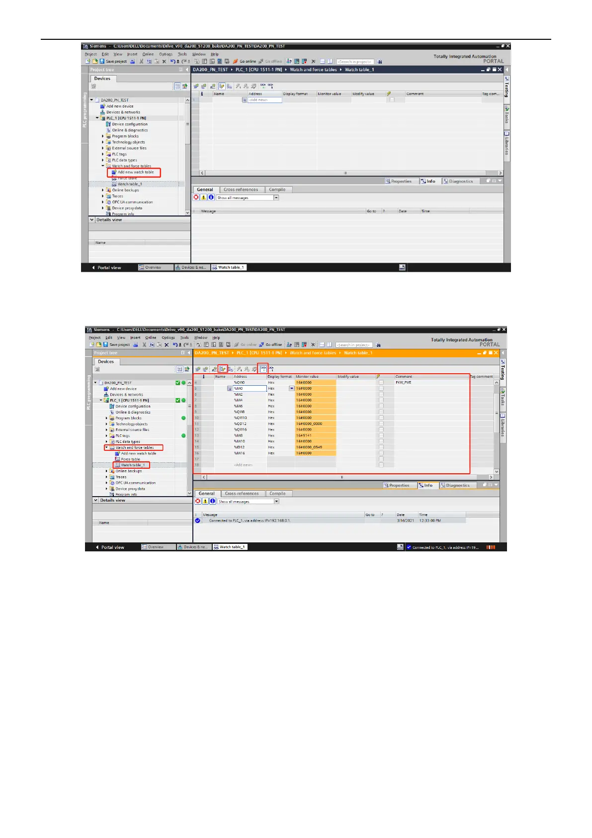
QW0–QW31 correspond to the PLC output addresses, consistent with the Q addresses in the
configuration, while IW0–IW31 correspond to the PLC input addresses, consistent with the I addresses in
the configuration. You can monitor and modify the values.
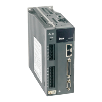
2.4 Configuring IRT communication
This section describes how to use S7-1500 PLC of Siemens TIA PORTAL V13 to configure PROFINET
IRT communication for the servo drive.
The following uses Siemens PLC S7-1500 as an example to describe the configuration process, which is
also applicable to the PLC with PROFINET interface with the IRT function.
2.4.1 Creating a project
Open TIA PORTAL V13, and create a project, which contains one PLC S7-1500, two DA200 servo drives,
to which INVT I/O sub modules are added. Set the IP addresses and device names of S7-1500 and
DA200. Assign device names invt-1 and invt-1_1 to the two DA200 servo drives online. The project is as
shown in the following figure.
 Loading...
