INVT SV-DA200 AC Servo Drive PROFINET Technical Guide V2.63
2
Standard RJ45 interface function table
Port2: The network is not connected.
Port 2: The network communication is
normal.
Port2: The network has been
connected.
Port1: The network is not connected.
Port 1: The network communication is
normal.
Port1: The network has been
connected.
PROFINET communication normal
PROFINET communication fault
CN3 interface LED indicator definition table
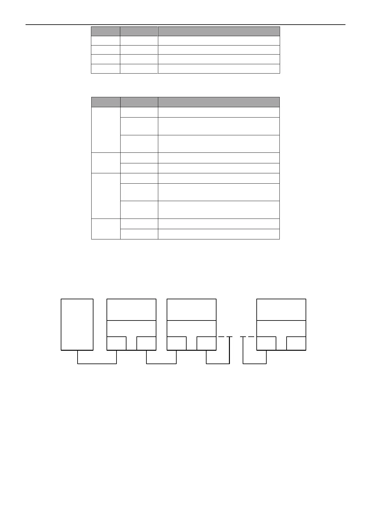
1.2 Electrical connection
With standard RJ45 interfaces, the servo drives can use the linear network topology or star network
topology. The electrical connection diagrams are shown as follows.
Master
node
Slave node 2
RJ45
RJ45
Slave node 1
RJ45
RJ45
Slave node n
RJ45
RJ45
DA200DA200 DA200
Linear network topology electrical connection diagram
Note: For the star network topology, you need to prepare PROFINET switches.
 Loading...
