en-33
JACOBSEN G-PLEX III Series: FH & FJ
SAFETY AND OPERATORS MANUAL
8 SETUP
8.4 CUTTING CYLINDER LIFT & LOWER
RATE & SYNCHRONISATION
The valves that control the rate and sequence in
which the cutting units rise and fall are set at the
factory, however they can be reset or altered using
the following steps.
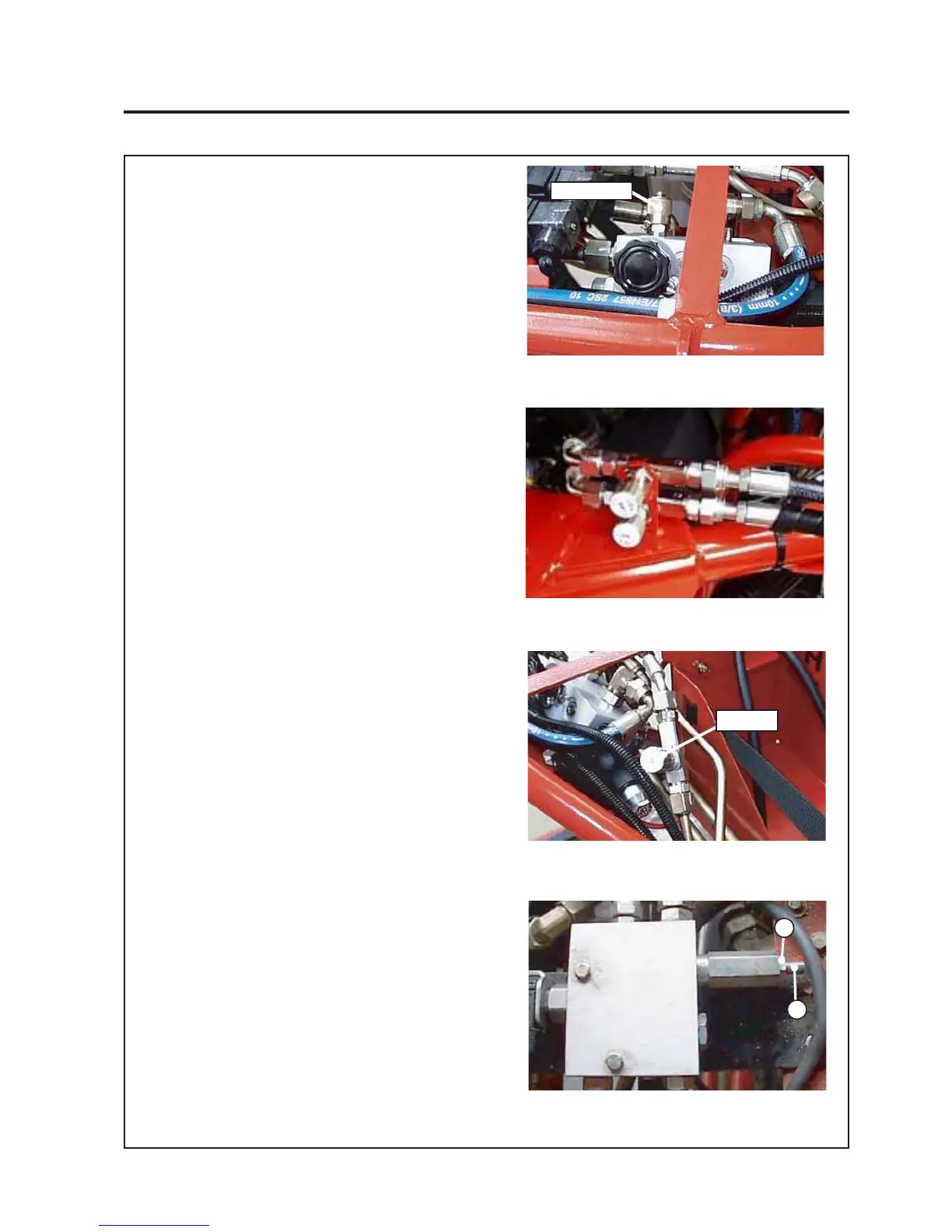
1. Attach a suitable hydraulic pressure gauge to
the port on the cylinder reel drive valve (see
Fig.8.4.1).
2. Start the machine and run the engine at full
throttle for 15-20 mins to ensure that the oil is
at the optimum temperature.
3. Screw both the centre unit lift and lower
valves found at the rear of the machine in
CW all the way. Then screw the top valve out
one and a half turns and the bottom valve out
one turn (see Fig.8.4.2).
4. Screw the front units lower valve found under
the battery cover out CCW all the way and
then in one complete turn (see Fig.8.4.3).
5. The pressure relief valve setting on the lift
valve needs to be set to 1275 ± 75 psi. To
check this raise and lower the cutting
cylinders and note the peak pressure reading
on the pressure guage attached to the
cylinder reel drive valve.
If the gauge displays a pressure outside the
limits specified above the pressure needs to
be corrected. This is done by first losening
the nut on the pressure relief valve (see item
1 on Fig.8.4.4) and then adjusting the valve
setting screw (item 2). Screw the screw in to
increase the pressure and out to decrease
the pressure. Adjust the screw half a turn at
a time and re-check the pressure by raising
and lowering the cutting cylinders. Once the
optimum pressure is reached retighten the
locking nut (item 1) to secure the setting.
6. Cycle the cutting units to check the
synchronisation. The centre cutting unit
should lower and lift slightly after the front
cutting units.
Fig.8.4.1
Gauge Port
GAUGE PORT
Fig.8.4.4
Pressure Relief Valve
Fig.8.4.3
Front Unit Lower Valve
1
2
2
VALVE
Fig.8.4.2
Centre Unit Lift & Lower Valves
 Loading...