Page 20
1. If connecting a Low Voltage pool heater (for example, a Jandy
®
brand heater),
connect two (2) 14 gauge wires, designed for use in hot environments, to
the proper terminals on the 10 pin terminal bar (see Figure 4). If you are
connecting a High Voltage pool heater, contact Zodiac for instructions.
2. Bring the two (2) heater wires from the PCB over to the heater and wire nut in
series with heater circuitry as if you were wiring a reman’s switch or a heater
delay.
3. Turn the heater thermostat to the Spa position and maximum setting.
4. Turn the heater toggle switch on.
5. Do not disconnect the high limit or pressure switches.
NOTE For Spa Heater, make connection to the Spa heater Interface
Board and plug it into the Spa Heater socket.
5.6 Connecting Auxiliary Equipment to PCB
Connect the high voltage relay plugs into their appropriate sockets according
to the wiring diagram located on the inside of the Power Center door.
NOTE This appliance has up to 9 supply connections.
NOTE Pool filter pump socket is on the far left of the PCB and the spa
filter pump relay socket is on the right after AUX 6 socket.
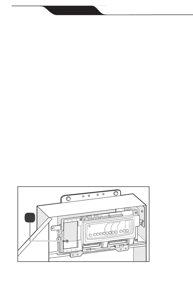
5.7 Finalize Hardware Installation
1. Install retaining screw on top left of AquaLink RS Conversion Kit chassis, see
Figure 16(a).
Figure 16 AquaLink RS Conversion Kit Mounting
Jandy
®
AquaLink
®
RS Conversion Kit

 Loading...