Page 20
Page 21
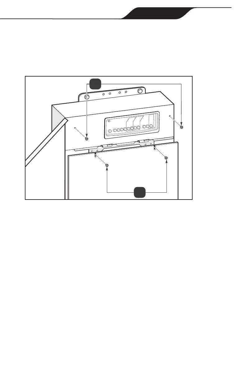
2. Secure AquaLink RS Conversion Kit cover with 2 screws, see Figure 17(a).
3. Align tabs on bottom of low voltage dead front to the slots in the power center
enclosure.
4. Secure the cover panel to the power center using the screws removed in
section 2.4, see Figure 17(b).
Figure 17. AquaLink
®
RS Conversion Kit Cover
5.8 Test the Equipment
Testing of the equipment is recommended before the automation system is put
into service.
1. Use the multimeter to check continuity to ground for all metal parts.
2. Put the system into Service mode.
3. While in Service mode each auxiliary can be toggled to ensure that the
equipment is functioning and that it is connected to the correctly labeled AUX
on the PIB.
4. Ensure all enclosure openings are closed and sealed for water ingress
protection.
Section 6. Program DIP Switch Settings
Two sets of DIP switches (S1 and S2) exist to control system conguration. The
DIP switches are monitored constantly by the system and if they are changed it is
immediately recognized. Restarting the system is recommended to ensure all of the
settings get updated.
Installation & Operation Manual

 Loading...