Do you have a question about the Jandy AquaLink RS Conversion Kit and is the answer not in the manual?
| Compatibility | Jandy AquaLink RS systems |
|---|---|
| Function | Converts existing AquaLink RS systems to modern control platforms |
| Connectivity | Wi-Fi |
| Power Requirements | Existing AquaLink RS power supply |
| Remote Access | Yes, via Jandy AquaLink app or web interface |
Covers warnings about pressure, electric shock, child drowning, and accidental drowning.
Emphasizes qualified installers and providing manual to owner/operator.
Details grounding requirements and safe wiring practices for electrical shock prevention.
Warns about chemical compatibility with pool materials and proper chemical mixing.
Advises on using quality stainless steel and proper sealing of masonry products for pools.
Explains risks of prolonged immersion in hot water, hyperthermia symptoms, and safe temperature limits.
Covers drug/alcohol use, medication, pregnant women, and electrical appliance placement.
Discusses gas heater installation, CO risks, FCC compliance, and general installation precautions.
Details hazards of pump suction and requirements for suction outlet covers and installation.
Specifies the number and spacing of suction outlets per pump for safety.
Outlines maximum water velocity through fittings and compliance with ANSI/ASME standards.
Lists standards for which the conversion kit is ETL Classified.
Provides a detailed list of items included in the AquaLink RS Conversion Kit.
Lists Pentair systems compatible with the conversion kit and notes on saltwater systems.
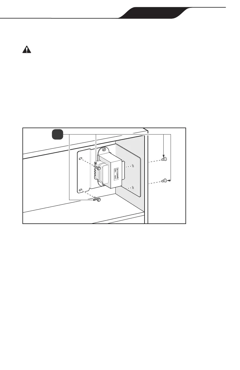
Instructions for removing the transformer when located within the control panel compartment.
Details on disconnecting power, valve actuators, Ethernet, and auxiliary relays.
Steps for removing the transformer assembly and the Pentair control panel.
Instructions for removing the transformer when it's located on the high voltage side.
Procedures for disconnecting power, valve actuators, Ethernet, and auxiliary relays from high voltage.
Instructions for placing the AquaLink RS Conversion wiring diagram label correctly.
Steps for installing the new Jandy Aqualink transformer using the provided bracket.
Procedures for securing the conversion kit hinge and PIB bracket.
Plugging in valve actuators, auxiliary, and RS-485 to the conversion kit panel.
Connecting water, air, and optional solar sensors to the green terminal bar.
Guidelines for connecting millivolt, electronic ignition, or 24 VAC heat pumps.
Instructions for connecting low voltage and high voltage pool heaters to the PCB.
Connecting high voltage relay plugs for auxiliary equipment to the PCB sockets.
Securing the AquaLink RS Conversion Kit chassis and cover using retaining screws.
Procedures for testing continuity, service mode, auxiliary function, and enclosure sealing.
Explains the purpose of DIP switches (S1, S2) for system configuration and recognition.
Details functions for S1 DIP switches, controlling pool cleaner, spa pump speed, and heater cool down.
Provides a table detailing OFF/ON settings for S1 and S2 DIP switches for various functions.
Lists optional accessories compatible with the AquaLink RS Conversion Kit.
Explains how to configure DIP switches for SOLAR PRIORITY or HEAT PUMP PRIORITY.
Instructions for adding and programming the iQ20 Web Connection unit as the final installation step.