Operation
Instruments
37 9831/0650-3 37
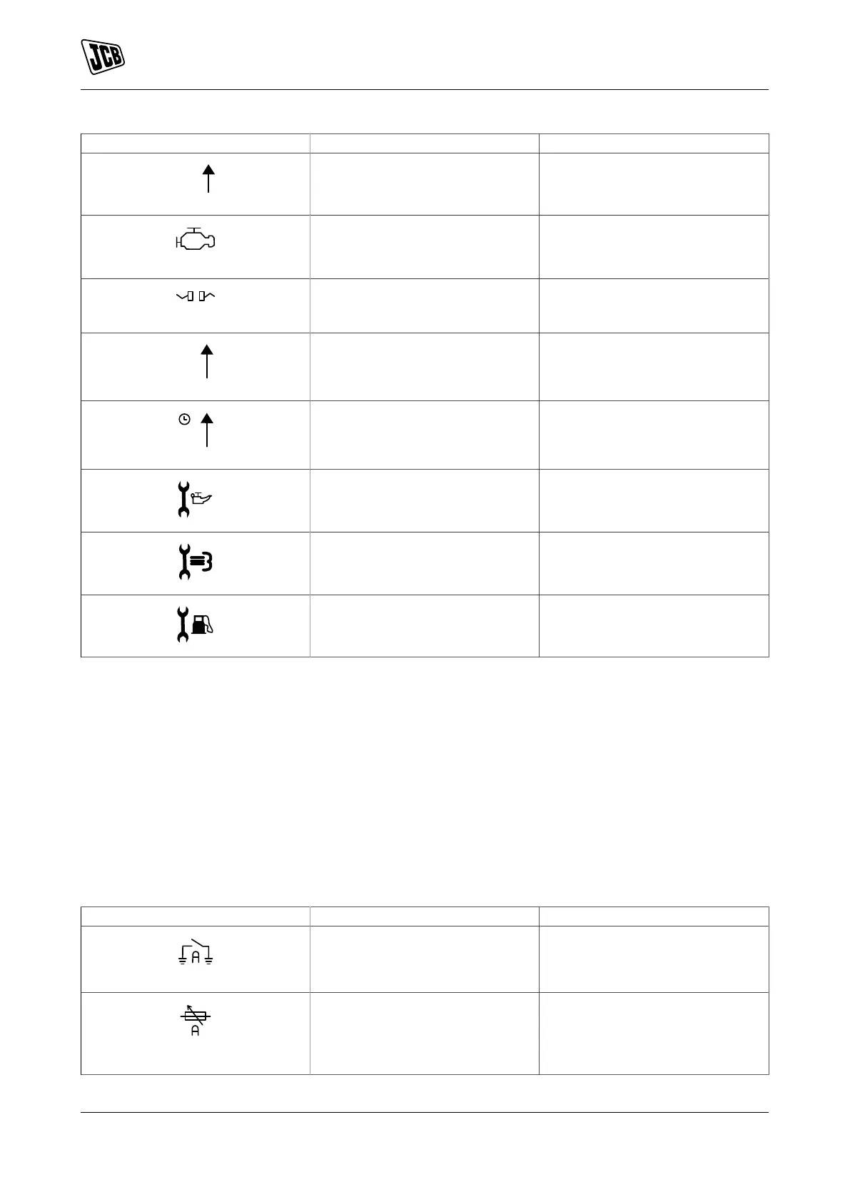
Icon Fault Description
Generator Over Frequency The generator output frequency
has risen above the pre-set pre-
alarm setting.
CAN ECU Fault The engine ECU has detected an
alarm.
CAN (Controller Area Network) Da-
ta Fail
The module is configured for CAN
operation and does not detect data
on the engine CAN data link.
Immediate Over Current The measured current has risen
above the configured trip level.
Delayed Over Current The measured current has risen
above the configured trip level for a
configured duration.
Oil Filter Maintenance Alarm Maintenance due for oil filter.
Air Filter Maintenance Alarm Maintenance due for air filter.
Fuel Filter Maintenance Alarm Maintenance due for fuel filter.
Electrical Trip Alarm Icons
Electrical trips are latching and stop the Generator but in a controlled manner. On initiation of the electrical
trip condition the module de-energises all the `Delayed Load Output' and the `Close Gen Output' outputs to
remove the load from the generator. Once this has occurred the module starts the Cooling timer and allows
the engine to cool off-load before shutting down the engine. The alarm must be accepted and cleared, and
the fault removed to reset the module.
Electrical trips are latching alarms and to remove the fault, press the STOP/RESET mode button on the module.
The alarm condition must be rectified before a reset will take place. If the alarm condition remains, it is not
possible to reset the unit (The exception to this is the Low Oil Pressure alarm and similar `active from safety
on' alarms, as the oil pressure is low with the engine at rest).
Table 10.
Icon Fault Description
Auxiliary Inputs The module detects that an aux-
iliary input which has been user
configured to create a fault condi-
tion has become active.
Analogue Input Configured as Dig-
ital
The analogue inputs can be con-
figured to digital inputs. The mod-
ule detects that an input configured
to create a fault condition has be-
come active.
 Loading...