9 - 15
Section C
Electrics
9803/6400
Section C
9 - 15
Issue 2*
Fault Finding
Fault Diagnosis (continued)
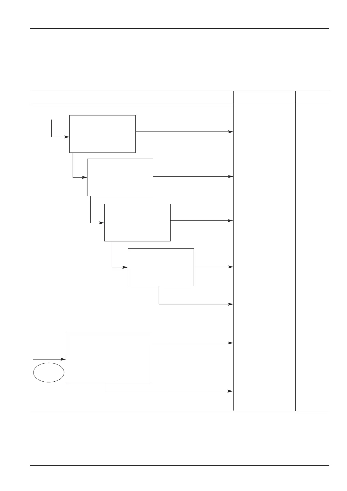
Electrical System, Message Fault, Problem No.10 (continued)
Note: Message does not go out.
Troubleshoot Cause Remedy
Breakage or defective
wiring between Repair
CNI and CN15 wiring
Breakage or defective
wiring between Repair
CNI and CN15 wiring
Breakage of wiring
P between CN15 Repair P
and fuse box wiring
Breakage of wiring
RY between CN15 Repair RY
and key switch wiring
Driver defect Replace
driver
Controller defect Replace
controller
Breakage of wiring
GY or GR between Repair
controller CN8 and GR or GY
driver CN15 wiring
Remove driver connector
CN15 and measure
resistances between female
side terminals R and B, R AND
G R and W, R and Y. Are they
within the range of 3.0~3.6 .
YES
YES
YES
NO
NO
NO
NO
Remove driver connector
CN15. Is it continuous
between female side terminals
GL and LgR?
Remove driver connector
CN15 and measure voltage
between female side terminals
P and BG, connecting P to +
and BG to -. Is it within the
range of 20~30V?.
Remove driver connector
CN15 and measure voltage
between female side terminals
RY and BG, connecting RY to
+ and BG to -. Is it within the
range of 20~30V?
Remove controller side connector CN8
and measure voltage between GY and
ground.
Is it 0V?
Measure voltage between GR and
ground.
Is it 5V?
Redundancy switch OFF, ignition switch ON
Continued from previous page
YES
Same work as *1
Ignition switch
YES
NO
YES
YES
Control System
Abnormalities
A
B
*
*
Ignition switch
*
*
*
*
*
 Loading...