107
(2) Power voltage changeover procedure (power voltage setting procedure)
WARNING :
To prevent personal injuries caused by electric shock hazards or abrupt start of the sewing machine,
carry out the work after turning OFF the power switch and a lapse of 5 minutes or more. To prevent
accidents caused by unaccustomed work or electric shock, request the electric expert or engineer of
our dealers when adjusting the electrical components.
q
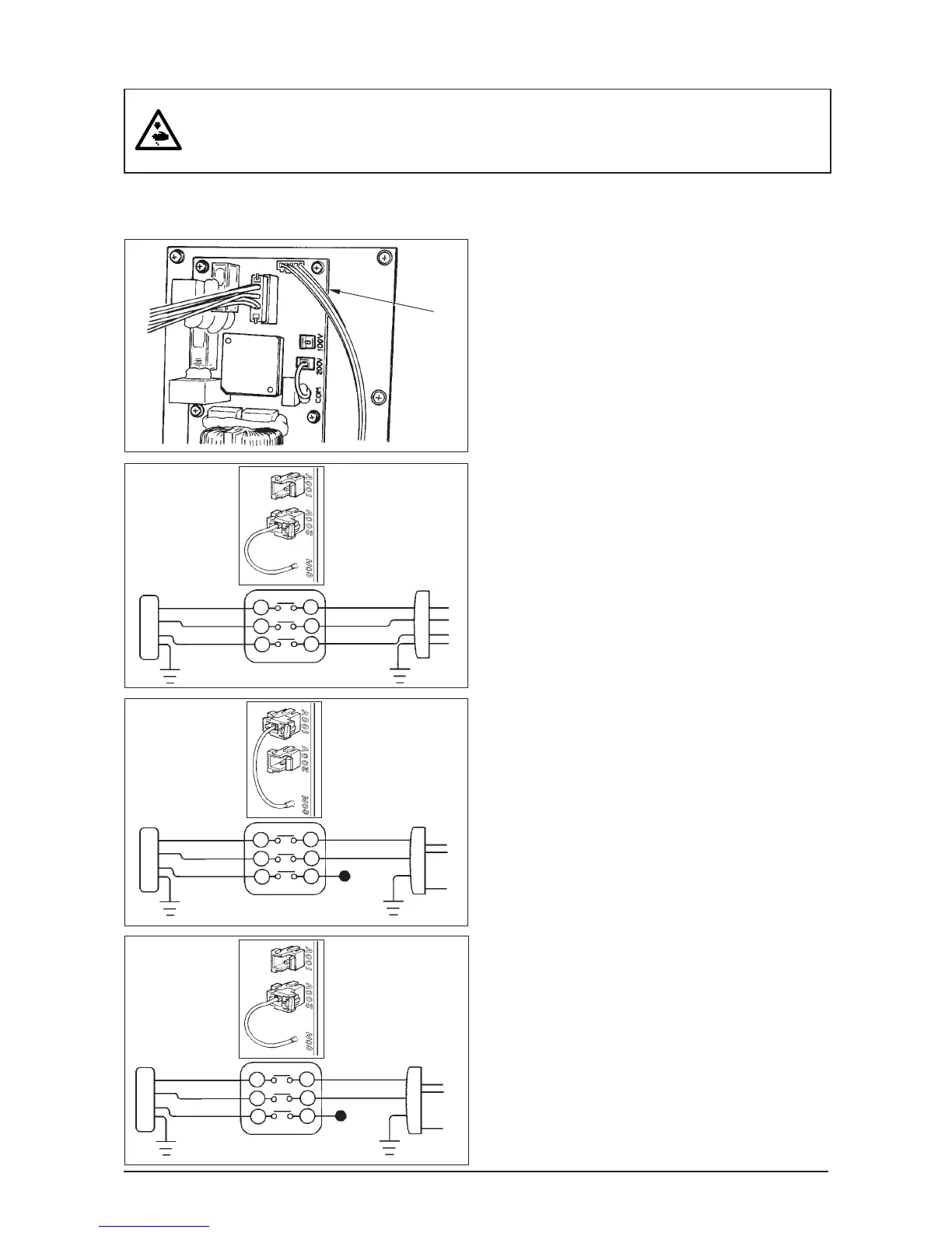
Changing procedure of the changeover connector
1. Turn OFF the power source with the power switch
after confirming that the sewing machine has
stopped.
2. Draw out the power cord from the power plug socket
after confirming that the power switch is turned
OFF. Then wait for five minutes or more.
3. Remove the front cover.
4. Remove four screws fixing the rear cover of the
control box and slowly open the rear cover.
A. In case of using with 3-phase 200V to 240V
• Changing the changeover connector
Connect to 200V the 100/200V changeover
connector of FLT p.c.b. q located on the upper
side of the right side face as observed from the
rear cover side.
• Connect the crimp style terminal of AC input cord
to the power plug as shown in the figure.
B. In case of using with single phase 100V to 120V
• Changing the changeover connector
Connect to 100V the 100/200V changeover
connector of FLT p.c.b. q located on the upper
side of the right side face as observed from the
rear cover side.
• Connect the crimp style terminal of AC input cord
to the power plug as shown in the figure.
(Caution) Securely perform the insulation
treatment to the black terminal which is not
used with insulation tape or the like.
(When the insulation is insufficient, there is a
danger of electric shock or leakage current.)
C. In case of using with single phase 200V to 240V
• Changing the changeover connector
Connect to 200V the 100/200V changeover
connector of FLT p.c.b. q located on the upper
side of the right side face as observed from the
rear cover side.
• Connect the crimp style terminal of AC input cord
to the power plug as shown in the figure.
(Caution) Securely perform the insulation
treatment to the black terminal which is not
used with insulation tape or the like.
(When the insulation is insufficient, there is a
danger of electric shock or leakage current.)
5. Check that the change has been performed without
fail before closing the rear cover.
6. Be careful that the cord is not pinched between the
rear cover and the control box main unit. Close the
rear cover while pressing the lower side of rear
cover, and tighten four screws.
It is adaptable to the voltage of single phase 100V to 120V/3-phase 200V to 240V by changing the voltage
changeover connector mounted on FLT p.c.b.
(Caution) When the changing procedure is wring, the control box will be broken. So, be very careful.
GREEN/
YELLOW
(Plug side)
WHITE
BLACK
RED
WHITE
BLACK
RED
GREEN/
YELLOW
GREEN/
YELLOW
(Plug side)
GREEN/
YELLOW
(Plug side)
GREEN/
YELLOW
GREEN/
YELLOW
A
B
C
WHITE
BLACK
RED
WHITE
BLACK
RED
WHITE
BLACK
RED
WHITE
BLACK
RED
 Loading...