– 48 –
6. CHANGING PROCEDURE OF THE PEDAL TYPE
(1) Parts necessary for change
Part No. Description Q’ty
M4009351000A Spring shaft B 1
M4011351000 Return spring B 2
M4012351000 Return pressure adjusting screw 1
M2010110000 Return pressure adjusting nut 1
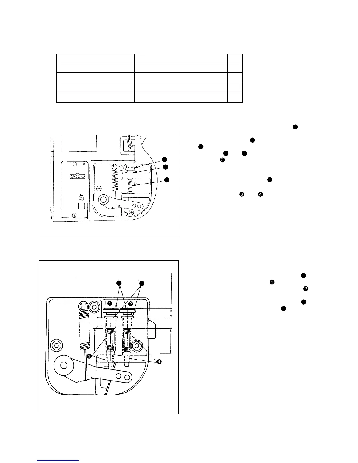
1. Loosen return pressure adjusting nut
b
in the
pedal sensor A asm. (Fig. 1), remove return pres-
sure adjusting screw
a
, remove return spring A
c
, and replace it with the return spring B. Then,
assemble
a
and
b
.
2. On side of pedal sensor B asm., assemble
spring shaft B, return spring B, return pressure
adjusting screw and return pressure adjusting nut
in the same manner as side .
Caution) Apply grease to the shaft sections of
sections and when assembling.
Perform adjustment of the height of spring changed
for the pedal type automatic presser foot lifter (PFL)
Adjust with return pressure adjusting screw
d
so
that the length of spring on side in Fig. 2 should
be 27 mm and that the length of spring on side in
Fig. 2 should be 28 mm. After the adjustment of
height, tighten return pressure adjusting nut
e
so
that return pressure adjusting screw
d
should not
become loose.
(2) Attaching parts
(3) Adjusting pedal depressing pressure
a
b
c
Pedal sensor A asm.
Pedal sensor B asm.
d
e
Perform to stop loosening
with adjusting nut.
Height of screw
(11 mm)
28mm
27mm
 Loading...