unnumbered IP interface (tied to the provider edge loopback interface) is stacked in the
context of the parent virtual router.
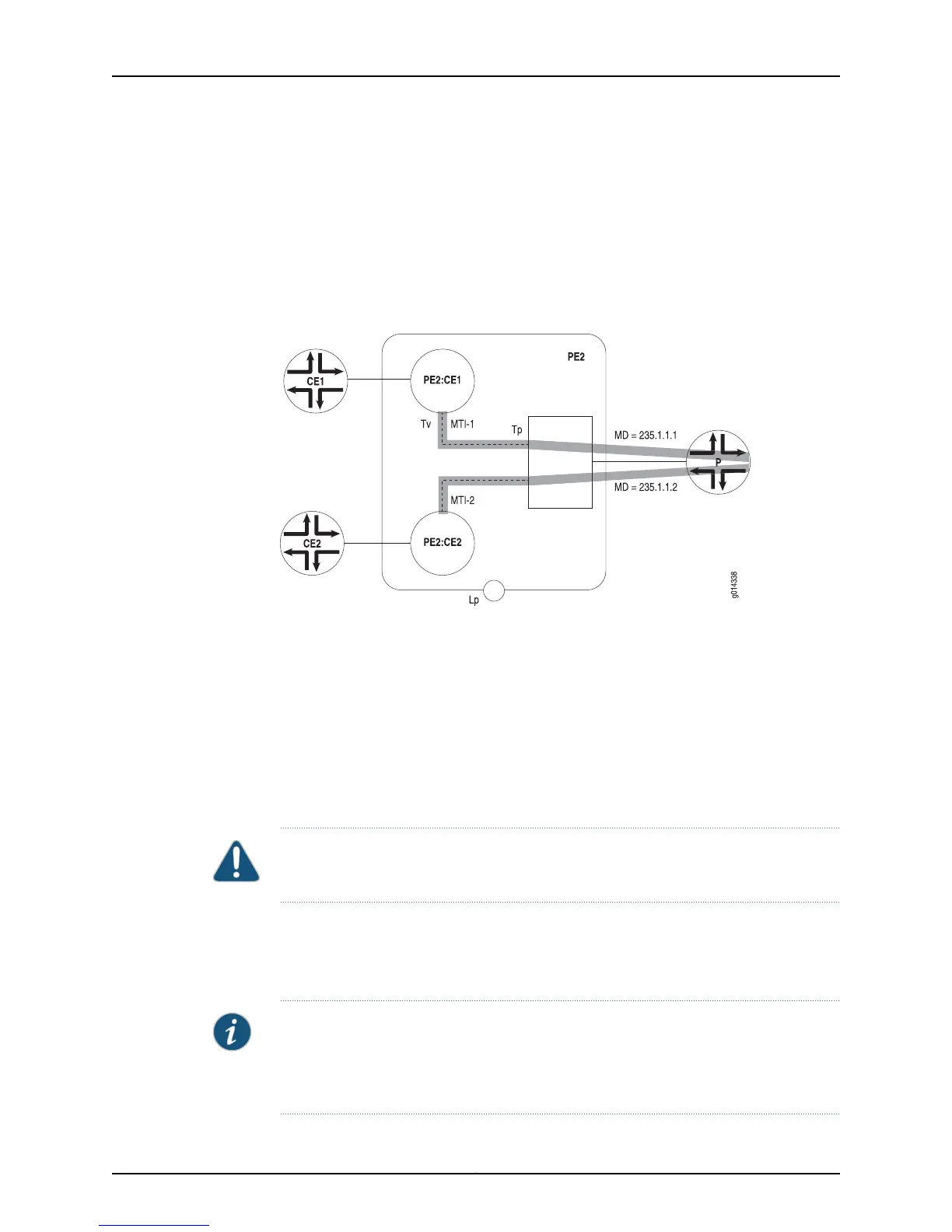
Multicast VPN Configuration Example
In the following example (Figure 13 on page 93), customer edge router 1 (CE1) and
customer edge router 2 (CE2) exist in two separate VPNs. Each VPN is configured with
its assigned Multicast Domain (235.1.1.1 and 235.1.1.2, respectively).
Figure 13: Multicast VPNs
To better understand the example, keep the following in mind:
•
Lp is a loopback interface in the parent router. This address is the loopback interface
used as the BGP peer address of the provider edge router (PE). Its address is advertised
in the provider address space.
•
Tv is the MTI in the VRF. This interface is typically configured as a PIM sparse-mode
interface (though you can configure it for dense-mode or sparse-dense-mode). Any
packets that originate in the VRF are sent using the address of this interface as the
source address. You must set this interface address to be identical to loopback interface
of the parent router (Lp).
CAUTION: Defining the Tv interface with an address other than the loopback interface
of the parent router might restrict operation with non-Juniper Networks routers.
•
Tp is an unnumbered IP interface that is tied to the loopback interface of the provider
edge router (PE).
To configure the example, use the following general procedures:
NOTE: This example provides general information for configuring a simple Multicast
VPN network. For detailed information about creating GRE tunnels, see Configuring IP
Tunnels in the JunosE IP Services Configuration Guide. For detailed information about
PIM sparse-mode configuration, see “PIM Sparse Mode” on page 80.
93Copyright © 2010, Juniper Networks, Inc.
Chapter 3: Configuring PIM for IPv4 Multicast
 Loading...