DCBA
4
5
3
2
1
Q5202
2SC4081/RS/-X
R5202
4.7K
5
4
3
2
1
DCBA
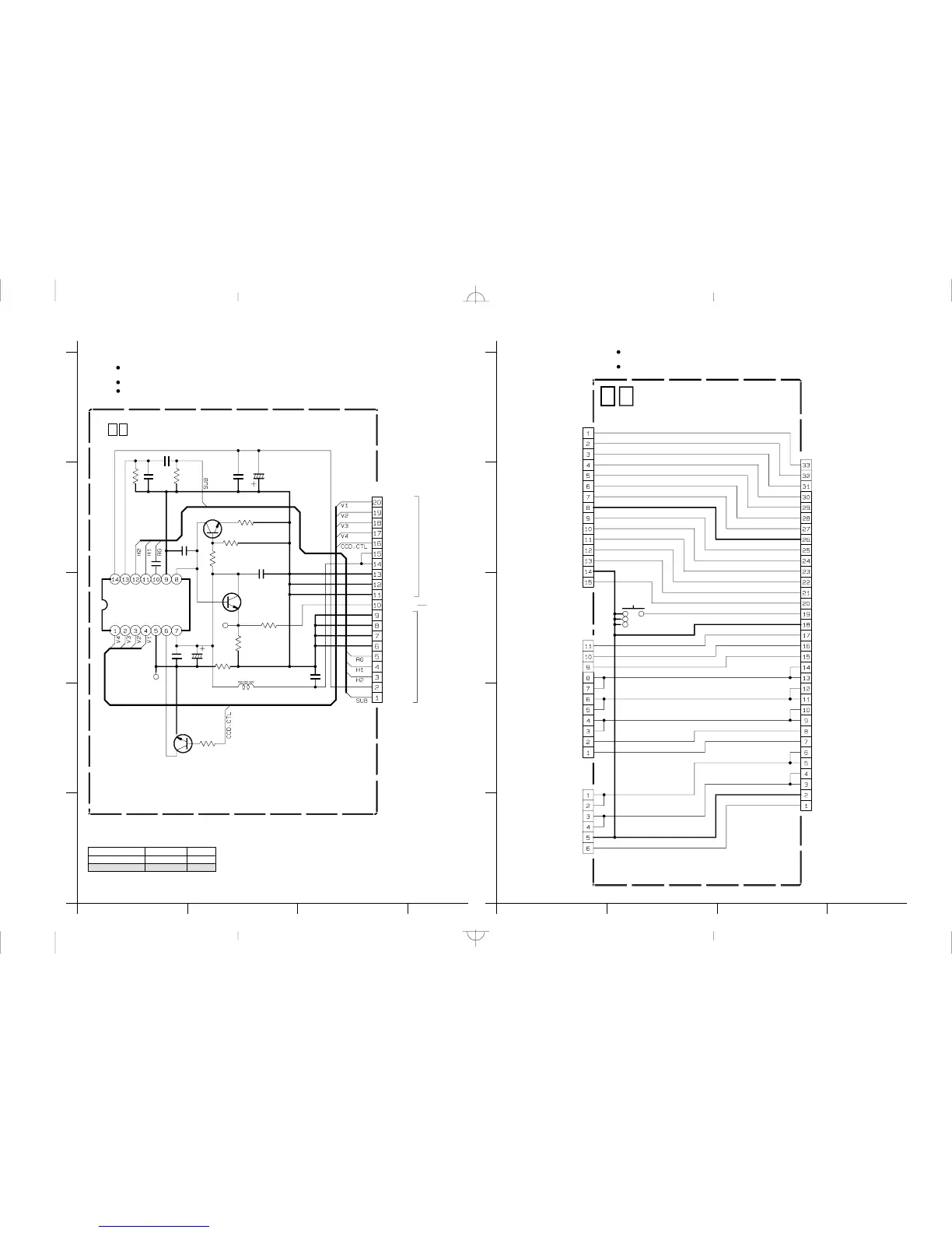
CCD SCHEMATIC DIAGRAM4.17 JUNCTON SCHEMATIC DIAGRAM4.18
4-364-35
C5205
C5210
R5204
Tl5202
Q5202
Q5203
C5211
R5205
R5206
CN5201
R5207
R5208
R5209
TL5203
C5203
C5208
R5202
IC5201
R5203
C5202
C5201
C5206
C5207
R5201
C5204
Q5201
L5201
0.1
0Ω
1
#
10K
12K
1K
0.1
0Ω
100k
10
0.1
0.1
2200p
4.7k
10
10µ
#
2SC3931/CD/-X
V1
V2
V3
V4
CCD_CTL
CCD_15V
CCD_15V
GND
GND
GND
CCD_OUT
GND
H2
CCD-7V
SUB
GND
H1
RG
GND
GND
V4
Vout
V3
V2
V1
GND
VSUB
Vdd
GND
RG
H1
H2
SUB
VL
/20
/10
2SC3931/CD/-X
∗
∗
T
T
∗
0 4 CCD
y30163001a_rev0
TO TG
CN107
TO CDS
CN107
TO TG
CN107
NOTE : The parts with marked ( ) is not used.
∗
# EXCHANGE PARTS LIST
With DSC MODEL
Without DSC MODEL
CN574
CN573
CN572
SW571
CN571
QGF0505F2-06X
QGF0505F2-11X
QGF0507F3-15X
NSW0120-002X
QGF0508F1-33X
LOAD_REV
TO SENSOR
JUNCTION
TO LOADING
LOAD_REV
LOAD_REV
LOAD_REV
LOAD_FWD
TO MAIN IF
CN113
LOAD_FWD
LOAD_FWD
LOAD_FWD
GND
GND
DEW_SENS
DEW_SENS
D_FG(-)
D_FG(-)D_PG(-)
D_PG(-)D_COIL_U
D_COIL_UD_COIL_U
D_COIL_UD_COIL_V
D_COIL_V D_COIL_V
D_COIL_VD_COIL_W
D_COIL_WD_COIL_W
D_COIL_WD_PFG(+)
D_PFG(+)COIL_COM
COIL_COMDR_GND
DR_GND
CAS_SW
GND
GND
CAS_SW
REC_SAFE
REC_SAFE
MIC3
MIC3
MIC2
MIC2
MIC1
MIC1
S_SENS
S_SENS
REEL_GND
REEL_GND
T_REEL
T_REEL
TREELLED
SREELLED
TREELLED
SREELLED
S_REEL
S_REEL
E_SENS
E_SENS
TAPE_LED
TAPE_LED
TAPE_GND
TAPE_GND
EJT_SW
05
EJECT SW
MOTOR
TO DRUM MOTOR
y40093001a_rev0
∗∗
When ordering parts
,
be sure to order according to the Part Number indicated in the Parts List.
For the destination of each signal and further line connections that are cut off from
this diagram
,
refer to "4.1 BOARD INTERCONNECTIONS".
NOTES :
When ordering parts
,
be sure to order according to the Part Number indicated in the Parts List.
IC5201 is incorporated in the CCD base assembly. When IC5201 needs replacement, replace
the CCD base assembly in whole because it cannot be replaced alone.
For the destination of each signal and further line connections that are cut off from
this diagram
,
refer to "4.1 BOARD INTERCONNECTIONS".
NOTES :
 Loading...