10
Getting Started
TK-C685WPE/TK-C686WPE
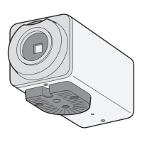
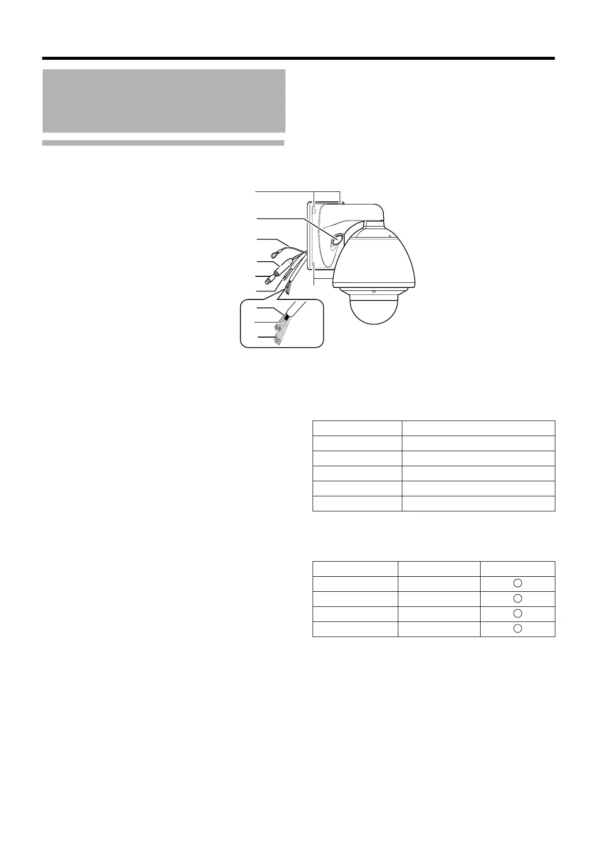
䡵 Camera
A Camera securing hole (x4)
This hole is used for mounting the camera on the wall.
B Cable connecting hole, cap
Remove the cap and pull out the cables from this hole for
connection. (A Page 27)
C Fall Prevention Wire
Connects the camera to the wall.
Secure the camera tightly to the anchor bolts used to mount
the fall prevention wire on the wall. (A Page 28)
D Protection Cover
Upon connecting the coaxial cable, slide it to cover the
connector E for coaxial cable connection. This cover
insulates the metal portion of the connector from the
structure inside the wall.
(A Page 28)
E Connector for Coaxial Cable Connection (BNC)
This is an output terminal for composite video signals (1 V(p-
p), output impedance 75 K). It connects switchers.
F AC24V Power Cable
This connects the camera to AC24V power. (A Page 28)
G Alarm Input 1/Alarm Output 1 Cable (5 cables)
Alarm Input 1, Alarm Output 1 Cable.
(A Page 32)
H Control Signal Connecting Cable (x4)
This connects the camera to the remote control unit (RM-
P2580). (A Page 32)
Name and Function of
Parts (continued)
A
B
C
D
E
F
H
I
A
G
Cable color Signal Name
GREEN/WHITE Alarm output 1 (OUT1NOP)
BLUE/WHITE Alarm output 1 (COM)
PURPLE/WHITE Alarm output 1 (OUT1NCL)
RED/BLACK Alarm input 1
ORANGE/BLACK Alarm input 1 (COM)
Cable color Signal Name Symbol
BROWN/WHITE TX +
RED/WHITE TX –
ORANGE/WHITE RX +
BLACK/WHITE RX –
A
B
C
D
 Loading...