22
Connection/Installation (TK-C685E/TK-C686E)
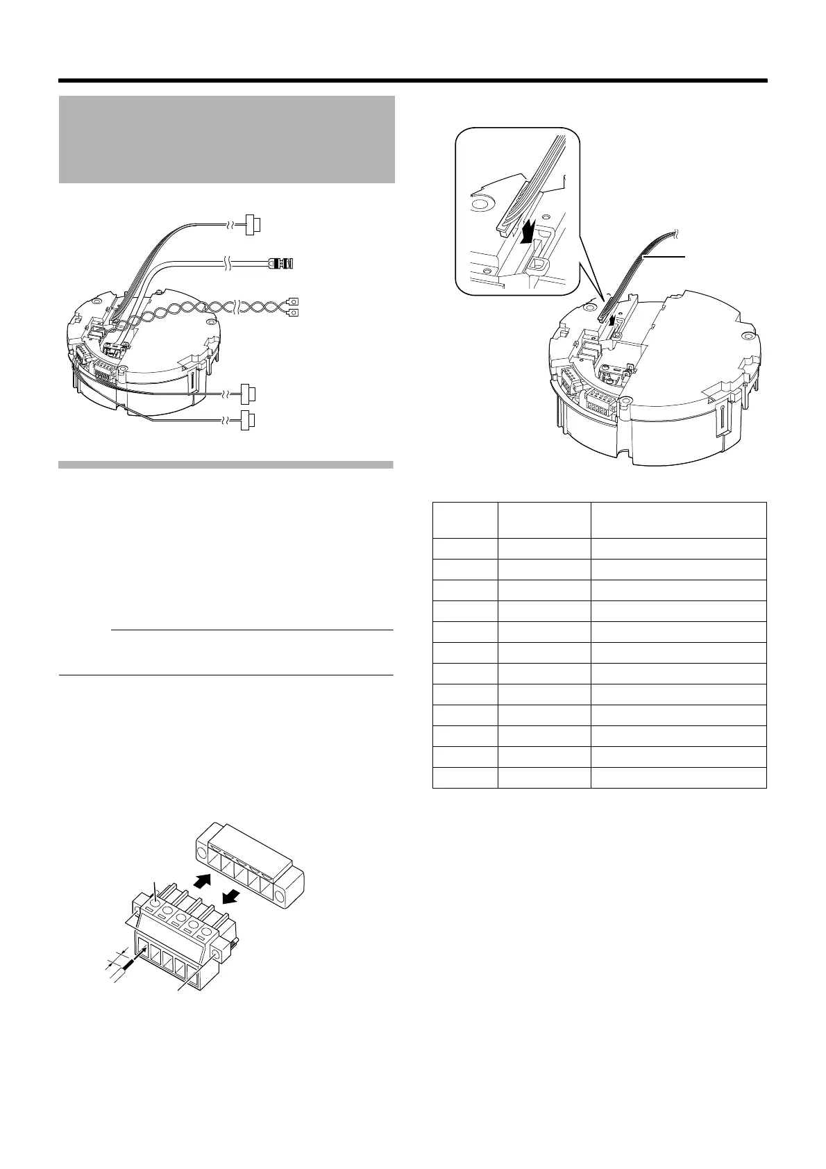
Connecting the alarm input/alarm output
terminals
䡵 Alarm input 1/Alarm output 1 terminal
Connecting alarm input 1/alarm output 1 terminal
to external devices such as sensor and buzzer
A Loosen screws on both sides of the terminal block with a
flathead screwdriver and remove the terminal block as
shown in the diagram below.
Memo :
● Inserting the tip of the screwdriver into the slit of the
terminal block will remove the terminal block easily.
B Peel off about 4 mm of the alarm signal cable covering
and insert into the terminal.
C Turn the screws at the side and secure the alarm signal
cable.
D When the alarm signal cable is secured, return the
terminal block that was removed in A to its original
position.
䡵 Alarm Input 2 to 6/Alarm Output 2 Terminal
Cable Connection
Alarm signal cable
Provided alarm cable
Control signal cable
Coaxial cable
Power cable
4 mm
A
B
C
A
D
Alarm signal cable
terminal
Pin
number
Cable color Signal Name
1 Brown Alarm input 2
2RedGND
3 Orange Alarm input 3
4YellowGND
5 Green Alarm input 4
6 Blue GND
7 Purple Alarm input 5
8GrayGND
9 White Alarm input 6
10 Black GND
11 Peach Alarm output 2+
12 Light green Alarm output 2–
Provided alarm
cable

 Loading...