32
Connection/Installation (TK-C685WPE/TK-C686WPE)
Connecting the alarm signal cable
䡵 Alarm input signal
Connects to sensors such as infrared sensors,
door sensors, metal sensors and manual switches.
● To prevent noise from entering the internal circuit, supply
non-voltage contact signal to the alarm input signal.
● Do not supply voltage.
● When the contact is short (MAKE) or open (BREAK) on
the menu, you can set it to Alarm.
● Supply such that the alarm signal continues for at least
more than 200 ms. The alarm signal may not be
recognized if it is less than 200 ms.
䡵 Alarm output signal
Connects to alarm devices such as alarm,
indicator, light or buzzer
● Alarm output 1 signal is the contact output. When there is
an alarm, the OUT1NOP-COM will become short (MAKE)
and OUT1NCL-COM will become open (BREAK).
● Alarm output 2 signal is an open collector output insulated
with photo coupler.
● During an alarm, it is ON.
● As this cable is polarized, be sure to connect it such that
the voltage of the + terminal is higher than that of the –
terminal.
● It will be damaged if reverse voltage is supplied.
Memo :
● When alarm is switched ON/OFF, a sound will be
produced from the alarm output 1 relay. If you do not want to
hear the sound, use the alarm output 2 cable. However, be
sure not to exceed the rating.
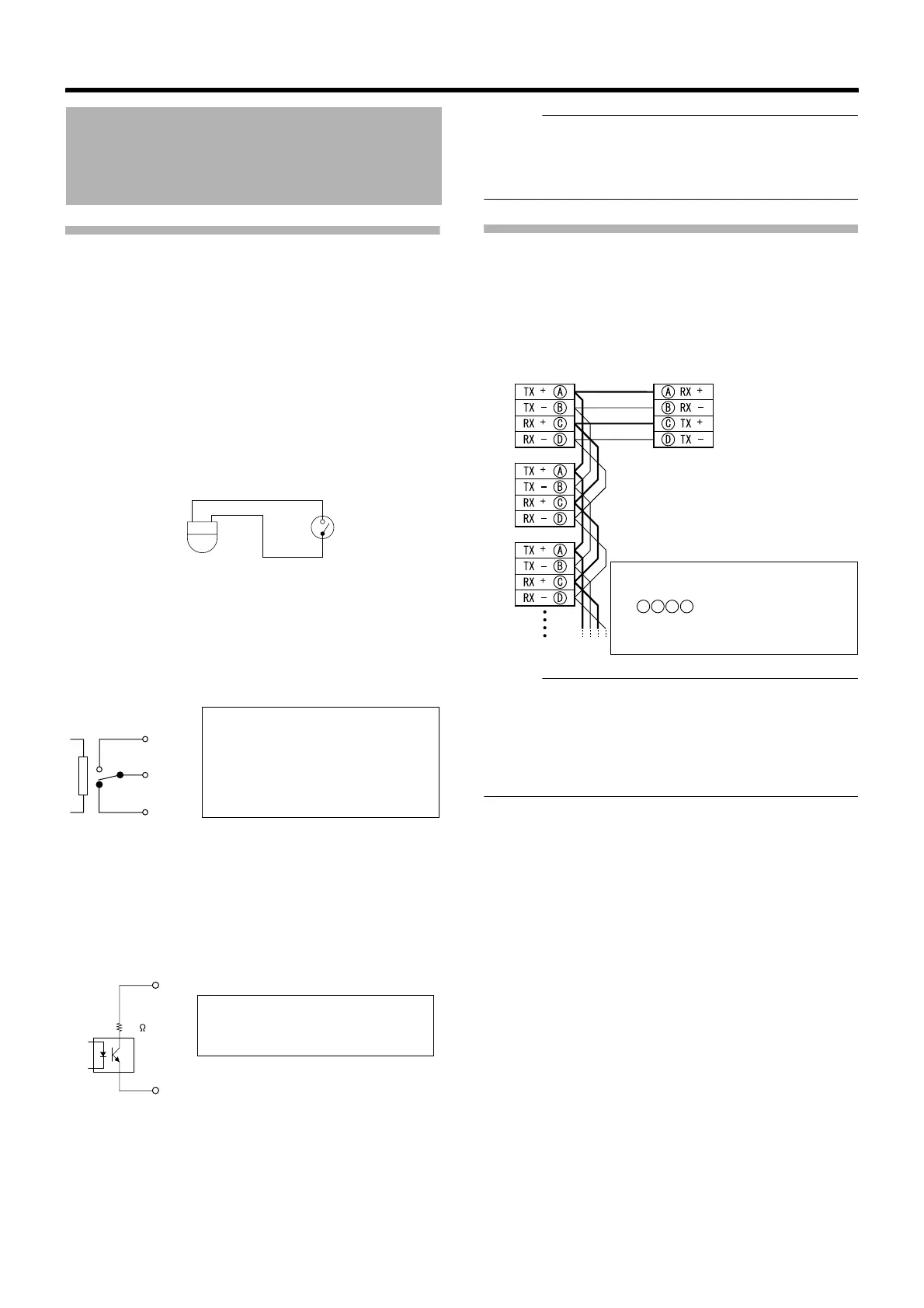
Connecting the control signal cable
The maximum connection distance with RM-P2580 is 1,200
m. (Multiple cameras can be connected on one cable for RM-
P2580 but the total length of the cable must be within 1,200
m.)
Memo :
● We recommend the use of paired cables or twisted pair
cables used in Ethernet rather than 0.61-4-core (2 pairs)
cables.
● Thickness of the cable is R0.4 mm to R1.3 mm.
● Arrange the control signal cables such that the TX+ and
TX–signals and RX+ and RX–signals are pairs.
Cable Connection
IN
GND
N.OPEN
COM.
N.CLOSE
Rating:
Max. applied voltage
:DC 30 V or AC 24 V
Max. applied current:1 A
Contact life :100,000 times
OUT +
OUT -
22
Rating:
Max. applied voltage:DC 20 V
Max. driving current:25 mA
● To connect correctly, connect
cables that have the same mark
as displayed on the
camera terminal and both
terminals of RM-P2580.
A
B
C
D
Camera terminal 1
Camera terminal 2
amera terminal 3
RM-P2580
TO CAMERA Terminal
 Loading...