Installing the inverter
Page Operating Instructions for Powador .-. TL_EN
ENEN
Authorised electrician
... Variant : activate the terminating resistor in the settings menu
. Open the menu.
. Select "Settings"/"Interface."
. Activate terminating resistor in the "Bus termination" menu entry.
. Conrm with "OK".
... variant . activate the terminating resistor with the switches on the circuit board
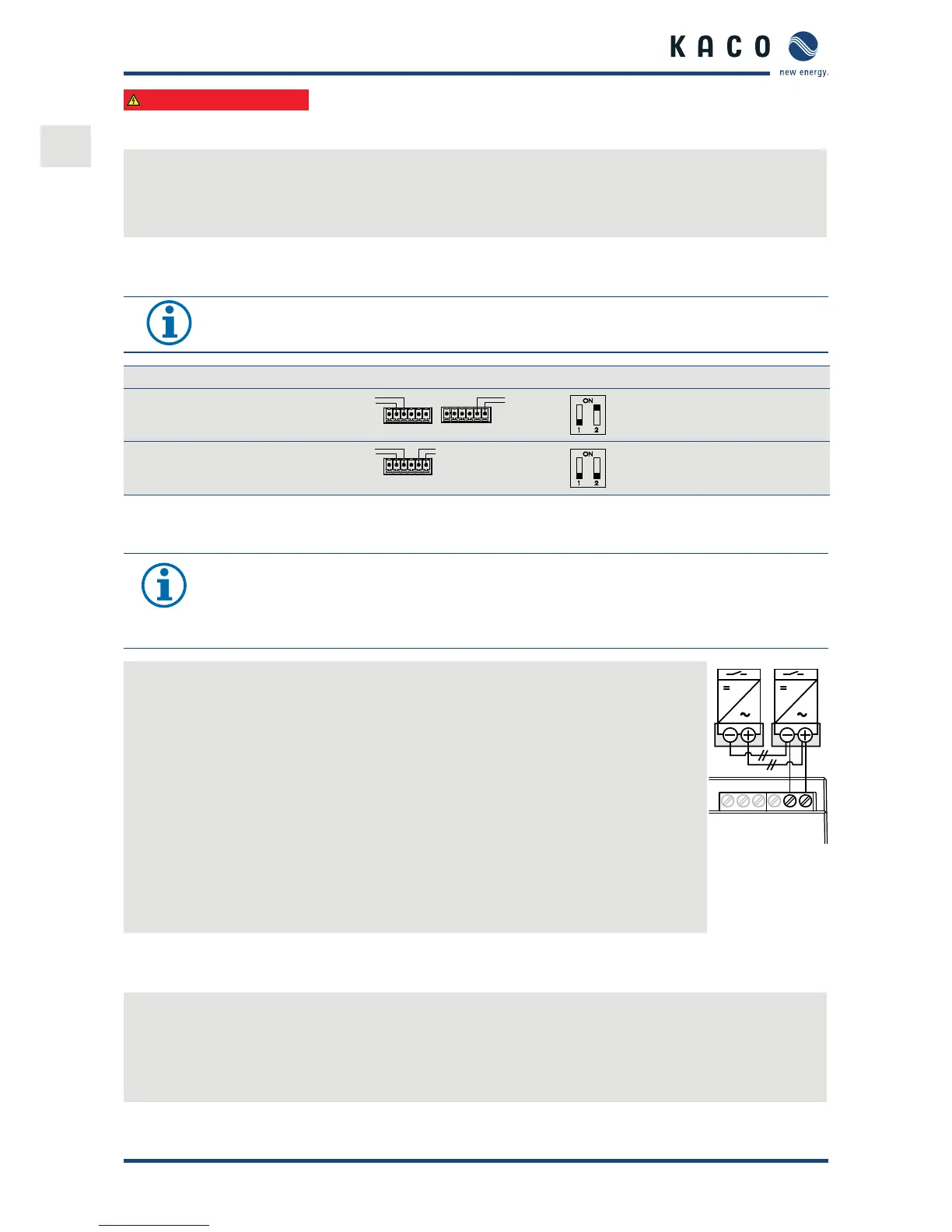
Activate the terminating resistor in the inverter that represents the terminal unit within your wiring diagram.
NOTE
Always activate the RS terminating resistor in the terminal using DIP switch .
Sample connection DIP switch Switch 1 Switch 2
The inverter is the terminal unit:
" Activate switch
B
A
B
A
,
B
A
B
A
OFF ON
The inverter is not the terminal unit:
" Deactivate switch
B
A
B
A
OFF OFF
.. Connecting "Inverter o" digital input (optional)
NOTE
The Powador-protect digital output can only be used with suitable KACO inverters. When using
devices from other manufacturers or in combination with KACO inverters, bus coupler circuit-break-
ers as a minimum must be used for shutting down devices from other manufacturers.
Connecting and activating "Inverter o" digital input
ඣ Can only be used with suitable KACO inverters.
. Unscrew the cable tting.
. Thread the connection cables through the cable tting.
. Connect wire A (+) to the "EVU+" or the marked terminal on the rst inverter via the "DO"
terminal of the Powador-protect.
. Connect wire B (-) to the terminal marked "EVU-" on the rst inverter via the "GND" termi-
nal of the Powador-protect.
. Connect the other inverters to one another as follows:
– wire A (+) to wire A (+) and wire B (-) to wire B (-).
D01
GND
4
3
2
1
. Tighten the cable tting.
. After commissioning: Activate the support for Powador protect in the parameter menu
under the "Powador-protect" menu item.
Figure : Pow-
ador-pro-
tect
. Sealing the connection area
. The requirements of protection rating IP are met by closing the unused cable ttings with blind caps.
. Put on the lid for the connection area.
. Close the housing door and lock it with a control cabinet key.
» The inverter has been mounted and installed.
» Start up the inverter.
 Loading...