GB - 14
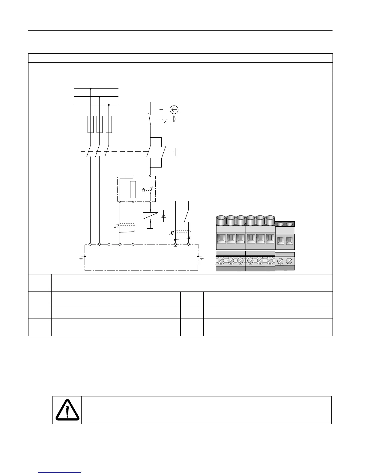
3.3.5 Wiring example braking resistor
Terminal strip X1B
Tightening torque 0.6 Nm (5 lb inch)
Connection cross-section 1.5…4 mm² (AWG 16-11)
S2
S1
L1
L2
L3
K1
K1
K1
2
L1 L2 L3
1
4
3
6
5
12
11
14
13
G
++
PB
OH1
OH2
PE
F
*)
(T1) (T2)
I1 COM
RB
+24VDC
– – PB
++
U V
W
T1 T2
T1 T2
*) Temperature input T1/T2 can also be used instead of terminals I1/COM. Temperature
input T1/T2 is activated as described in annex A.5.
F Main fuses S1 Push-bottom switch for switch on
K1 Line contactor with auxiliary contacts S2 Emergency-off switch
G KEB COMBIVERT B6 RB Braking resistor with temperature
monitoring
3.3.6 Note to the function
In the example above the locking of the line contactor K1 is interrupted in case of overhe-
ating of the braking resistor. The line contactor drops and switches off the mains voltage.
The auxiliary contacts 13/14 open the error linkage circuit at terminals I1/COM (T1/T2) and
release an error. The modulation is switched off. Thus the drive in generatoric operation
does not regenerate further energy into the DC link circuit.
Depending on the case of application (e.g. no generatoric operation) simple
circuits can be used. See chapter 7 for instructions of the download. Input I1
must be programmed and inverted in the application mode to "external error".
 Loading...