GB - 17
Installation and Connection
3.5 Control board xxB6Bxx-xxx (CAN)
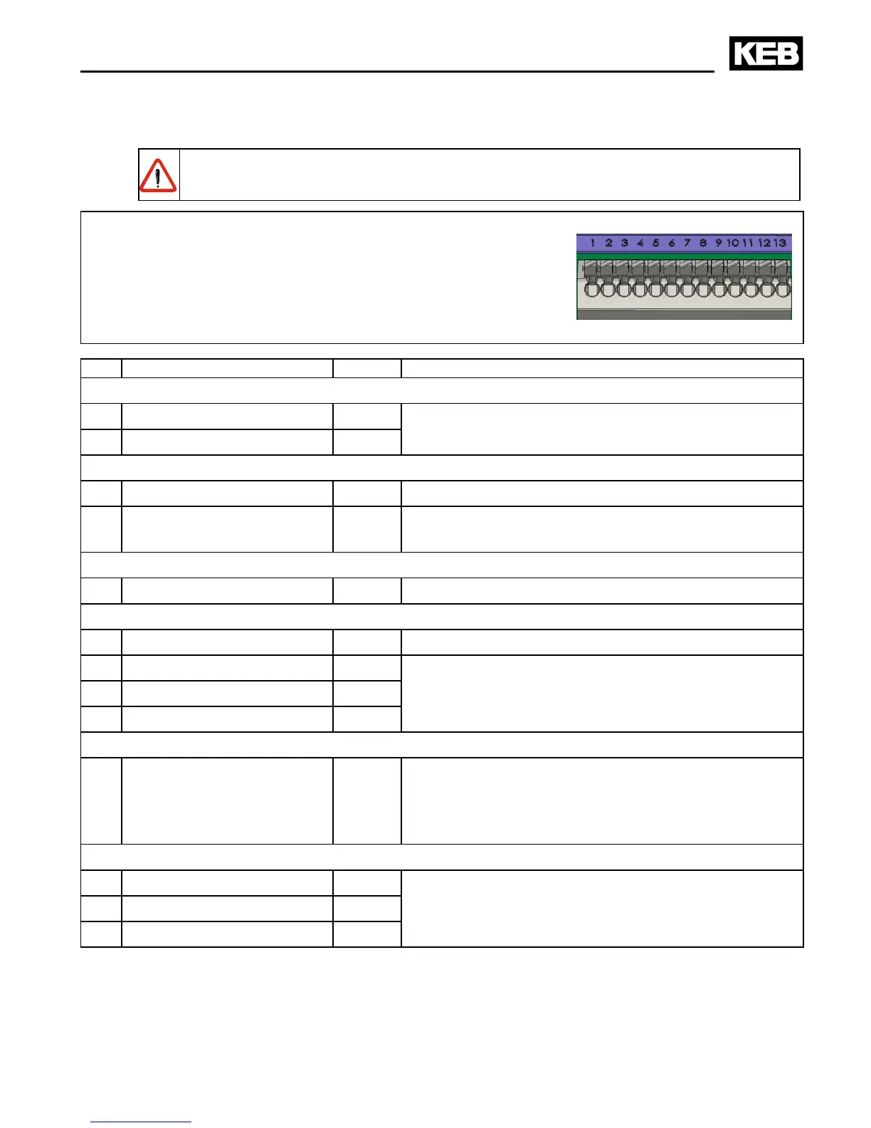
3.5.1 X2A Control terminal strip
The control connections are „safety separated circuits“ according to PELV requi-
rements.
• Conductor cross-section AWG 20-16 X2A
rigidly or exibly 0.5…1.5 mm²
Wire-end ferrule without plastic case 0.5…1 mm²
Wire-end ferrule with plastic case 0.5 mm²
• Strip length 8 mm
• Use shielded / drilled cables
• Lay shield on one side of the inverter onto earth potential
PIN Function Name Description
CAN interfaces
1 CAN high CAN-H Input and output of the CAN bus are parallel con-
nected to the corresponding terminals high and low.
2 CAN low CAN-L
Voltage supply
3 Mass COM Mass for digital inputs/outputs
4 +15 V Output +15V Stabilized supply voltage for digital inputs and set-
point poti +15 V DC ±8 % / max. 50 mA
Programmable digital inputs 13…30 V DC ±0 % smoothed; Ri: 2.2 kΩ; scan time: <=10 ms
5 Control release / Reset ST Power modules are enabled; reset at opening
CAN interfaces
6 CAN shielding CAN Connection for shielding of the bus cables.
7 -reserved- –
8 -reserved- –
9 -reserved- –
Programmable digital output 15 V DC ±10 % max. 50 mA
10 Digital output O1 Frequency dep. switch (factory setting)
Output switches at actual frequency = setpoint
frequency
Programmable with CP.32
Programmable relay output max. 30 V DC / 0.01…1 A
11 Relay 1 / NO contact RLA
Fault signalling relay (factory setting)
Programmable with CP.33
12 Relay1 / NC contact RLB
13 Relay1 / switching contact RLC
 Loading...