GB - 28
Error and Status Display
6. Error and Status Display
At KEB COMBIVERT error messages are always represented with an "E." and the appropri-
ate error in the display. Error messages cause the immediate deactivation of the modulation.
Restart possible only after reset or autoreset.
Malfunction are represented with an „A.“ and the appropriate message. Reactions to
malfunctions can vary. In the following the display and their cause are described. Status is
displayed witout any additions.
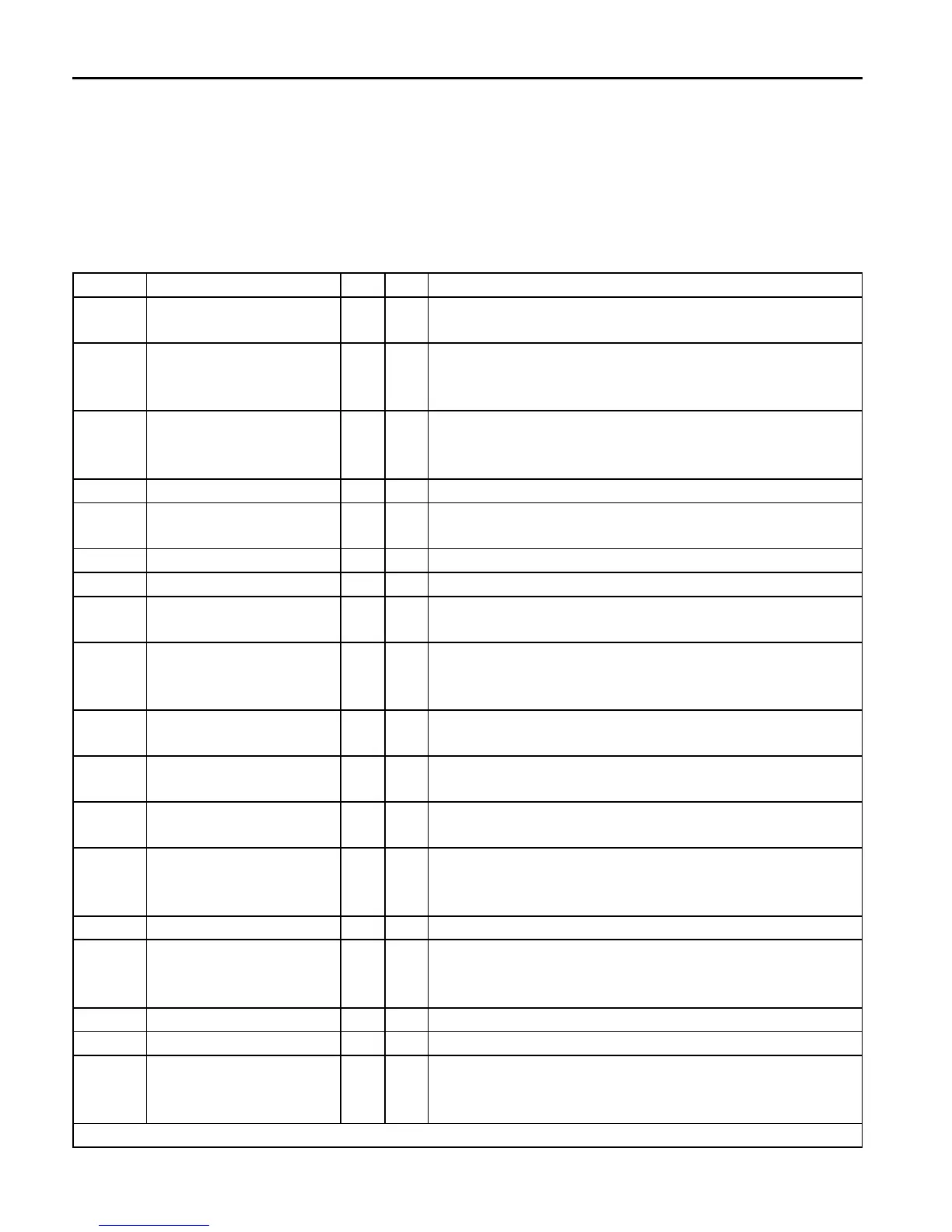
Display COMBIVIS display dec hex Meaning
bbL base block 76 4C The power modules for motor-de-excitation are locked
after opening the control release or after an error.
boFF open brake 86 56 This message is depending on the adjustment of
the brake control mode. It is displayed during open
(release) the brake.
bon close brake 85 55 This message is depending on the adjustment of
the brake control mode. It is displayed during close
(engage) the brake.
Cdd calculate drive data 82 52 Measurement of the motor stator resistance.
Cddr calculate drive data
ready
127 7F Measurement of the motor stator resistance success-
ful completed.
dcb DC brake 75 4B Motor is decelerated by a DC-voltage at the output.
dLS low speed / DC brake 77 4D Modulation is switched off after DC-braking.
FAcc forward acceleration 64 40 Acceleration with the adjusted ramps in clockwise
direction of rotation (forward).
Fcon forward constant 66 42 Acceleration / deceleration phase is completed and it
is driven with constant speed / frequency in clockwise
direction of rotation (forward).
FdEc forward deceleration 65 41 It is stopped with the adjusted ramp times in clockwise
direction of rotation (forward).
HCL hardware current limit 80 50 The message is output if the output current reaches
the hardware current limit.
LAS LA stop 72 48 This message is displayed if during acceleration the
load is limited to the adjusted load level.
LdS Ld stop 73 49 This message is displayed if during deceleration the
load is limited to the adjusted load level or the DC-link
current to the adjusted voltage level.
LS low speed 70 46 No direction of rotation pre-set, modulation is off.
nO_PU power unit not ready 13 0D This message is displayed if during deceleration the
load is limited to the adjusted load level or the DC-link
current to the adjusted voltage level.
noP no operation 0 0 Control release (terminal ST) is not switched.
PLS low speed / power off 84 54 No modulation after Power-Off.
POFF power off function 78 4E Is displayed during power-off function. Depending on
the programming of the function the inverter restarts
automatically upon system recovery or after a reset.
further on next side
 Loading...