3
ANTRIEBSTECHNIK
7
13
KEB COMBIVERT F4-F
Name: Basis
05.01.99
7
© KEB Antriebstechnik, 1999
All Rights reserved
Start-up
Section PageDate Chapter
P
OW
E
R
XX
XX
XX
XXX
XX
X
IN
PUT
O
UT
PUT
K
EB
Antrieb
stech
nik
Ka
rl E. B
rinkm
ann G
m
bH
D
-32
677
Ba
rn
trup
M
ade in
G
erm
an
y
VO
LT
AGE
CY
CLE
XX
XX
XXX
XX
XX
XX
XX
XX
XXX
XX
V
OLT
AG
E
C
U
R
R
E
N
T
V
ER-N
O.
A
R
T-N O .
S
ER
-N
O.
XXX
XX
XXX
XX
XX
XXX
˜
9
500000
1/XXX
XXX
X
XX
.F
4.X
XX
-X
XX
X
XX
XX
XX
XXX
XXX
X
XXX
XXX
XX
X
A
C
-M
OT
.
4,0 K
W, 2/ 4
P
, 50/60 H
Z
L1 L2 L3
2
3
S
T
AR
T
S
TO
P
EN
T
ER
F/R
FU
NC
.
SP
E
ED
ele
c
tro
n
ic
A
N
TR
IEB
S
T
EC
H
N
I
1
PO
W
ER
XXXX
XXX
XXX
XX
INP
UT
OU
TPU
T
KEB
A
ntriebs
technik
Karl E. Brinkm
ann G
m
bH
D
-3
26
77 Barntrup
M
ade in G
erm
any
V
O
LTA
G
E
C
YC
LE
XX
XXX
X
XX
XXX
XXX
X
XXX
X
XXX
V
OL
TA
GE
CURRENT
V
ER-NO
.
AR
T-N O
.
SER-NO
.
XX
XX
XX
XX
X
XX
XXX
X˜
9
500000
1/XX
XX
XXX
XX.F4.X
XX
-XX
XX
X
XXX
X
XXX
XXXX
XX
XXX
XXX
X
X
AC
-M
O
T.
4,0 KW
, 2/4 P, 50/60 H
Z
L1 L2 L3
S
T
A
R
T
S
T
O
P
E
N
T
E
R
F
/R
F
U
N
C
.
S
P
E
E
D
e
le
c
tro
n
ic
ANTRIEBSTECHNI
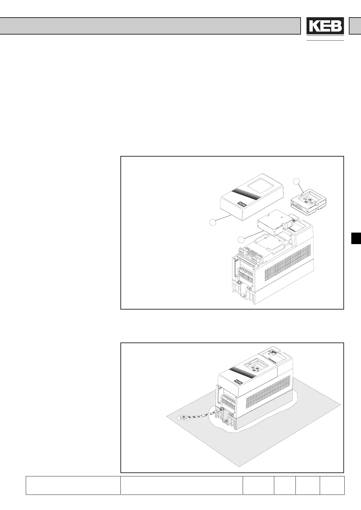
7.1.1 After unpacking
the Goods
7.1 Preparatory
Measures
7.1.2 Installation and
Connection
Picture 7.1.1 Insertion of operator (example based on D-housing)
7. Start-up
The following chapter is intended for everybody who has no experience with the KEB
frequency inverters. It shall allow a correct entering into this field. But because of the
complex application possibilities we must restrict ourselves to explaining the start-up
of standard applications.
After unpacking the goods and checking them for complete delivery following measures
are to be carried out:
; Visual control for transport damage
; Insert operator, if ordered
; Remove housing cover (1)
; Remove the dummy cap (2)
; Insert operator (3)
Picture 7.1.2.a Installation and connection
The EMC-conform installation of the inverter is described in the Instruction Manual
Part 1. Installation and connection instructions are found in the Instruction Manual
Part 2.
; The mounting surface of
the inverter must be
bright.
; If necessary, use contact
lacquer as protection
against corrosion.
; Connect the earthing
strip to central point in
the control cabinet.
Preparatory Measures

 Loading...
