Installation and Connection
8
2.3 Insulation Measuring
In order to prevent damages to KEB COMBIVERT the insulation measurements may
only be done in observance with important test conditions (see VDE 0558). The in- and
outputs of KEB COMBIVERT must be disconnected before insulation measurements
are done on the unit.
2.4 Connection of the Power Circuit
Dependent on the type of unit, not all power circuit terminals decsribed here are
available. A detailed description is found in the Instruction Manual for the Power
Circuit.
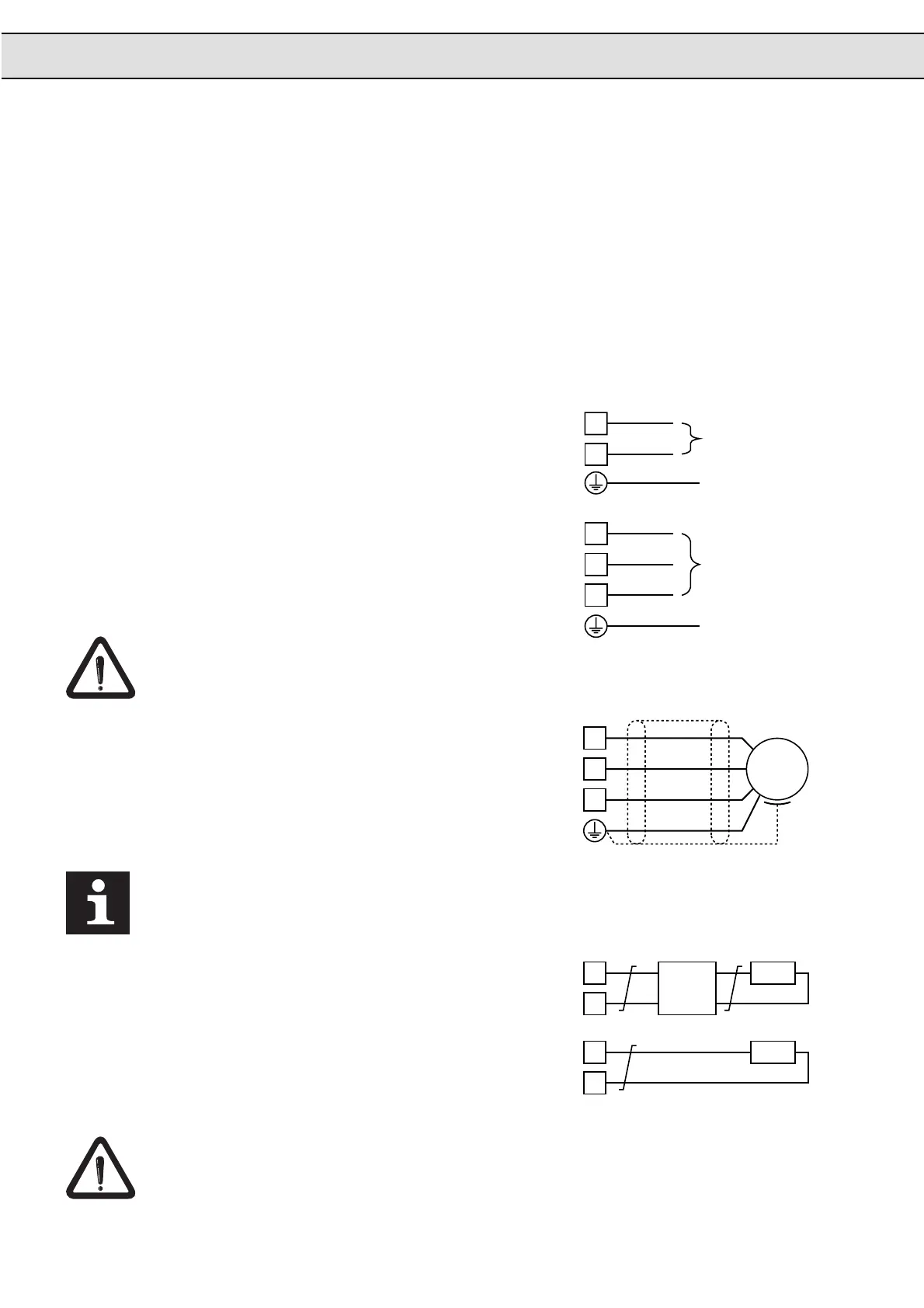
2.4.1 Mains Connection
1 - phase
(only 230V - class)
3 - phase
(230V and 400V class)
Exchanging the mains and motor connection causes immediate destruction of the unit.
2.4.2 Motor Connection
Note the supply voltage and
the correct polarization of
the motor!
With line lengths > 15m overvoltages can occur in the motor, which can endanger the
insulation system.
2.4.3 Brake Options
Connection Brake Module
Connection of the Braking
Resistor
(Internal Braking Chopper)
Never connected the braking resistor directly onto terminals
-
and
+
.
The terminals
+
and/or
PA
can also be characterized with
+/PA
.
L
N
L1
L2
L3
AC 180..260 V
50 / 60 Hz
AC 305..500 V
50 / 60 Hz
PE
AC 180..260 V
50 / 60 Hz
PE
U
V
W
M
3 ~
-
+
- PB
+ PA
PB
PA

 Loading...

