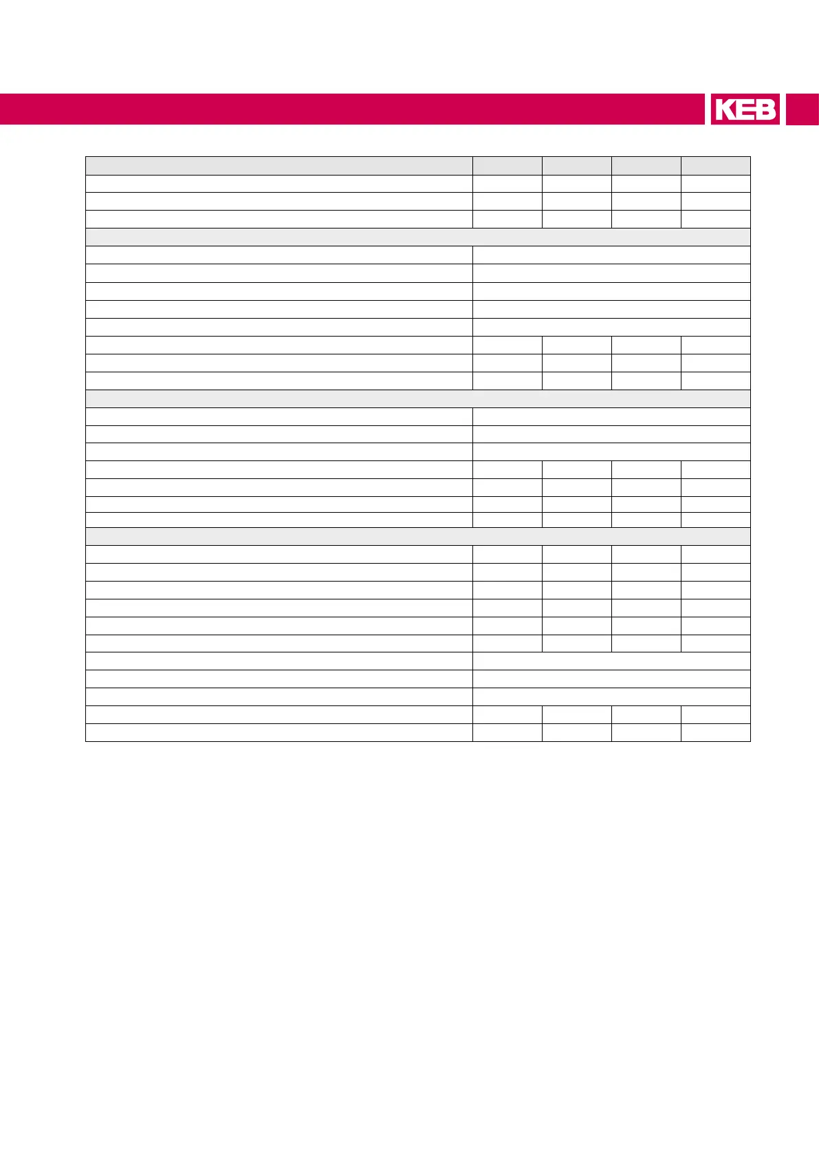
Device size 30 33 34 38
Housing size P P P P
Cooling mode (L=air; W=water) L L W W
Number of modules for master/slave 2 3 2 3
Input data
Mains phases 3
Permitted mains forms TN system
Rated input voltage U
N / V 400
Input voltage range U
in / V 340…480 ± 0%
Mains frequency f
N / Hz 50 / 60 ± 2
Rated input power S
N / kVA 395 554 616 1005
Rated input current I
N / A 2 x 285 3 x 267 2 x 445 3 x 483
Max. permissible mains fuse type gR / aR
2 x 400 3 x 350 2 x 630 3 x 630
Output data
Rated output voltage U
outN_dc / V 680
Output voltage range
2)
U_dc / V 530...840
Overvoltageswitch-o(E.OP) U
OP_dc / V 840
Power supply/regenerative rated current
3)
IoutN_dc / A 570 800 890 1450
Max. regenerative DC current 30 s I
out_max_dc / A 712 1000 1112 1813
Rated switching frequency f
SN / kHz 4
5)
4
5)
4
5)
4
5)
Max. switching frequency fS_max / kHz 4 4 4 4
Other data (referring to the rated data)
Overcurrentcut-o(E.OC) I
OC / % 150 150 150 150
Overload current (E.OL) 30 s I
OL / % 125 125 125 125
Max. permissible DC link capacity C
ext / mF 150
6)
250
6)
150
6)
250
6)
Max. AIC charging current (=> 6.5) IAIC / A 98
6)
145
6)
98
6)
146
6)
Max. external charging current (=> 6.5) Iext / A - - - -
Max. permissible total charging current (=> 6.5)
Ipre / A 98
6)
145
6)
98
6)
146
6)
Mains input circuit (=> 6.5) Type D1
Permissible DC fuses => „DC fuses“
Short-circuit factor at the connection point (S
kn / SN) 10 < Skn“ / < 350
Power dissipation at rated operation P
BR / W 4700 6900 7400 12000
Max. heat sink temperature t
_max / °C 90
7)
90
7)
90
7)
90
7)
1)
The input current of the
drive converter
must be limited to the rated current of the AIC / LCL lter, if
necessary.
2)
The operation is dependent on the voltage setpoint and the UOP limit (=> Programming manual).
3)
Measured at a reference voltage of 680 V DC.
4)
Limited by the rated current of the DC-terminal ! The input current must be limited to 300 A for input
voltages < 400 V.
5)
Must be set to 4 kHz for AIC operation (factory setting 2 kHz) !
6)
Option precharging resistor
=>
„Additional precharging resistor at master-slave operation“.
7)
Special settings are required for this device sizes (Reduction of the max. heat sink temperature
to 85°C,
=>
Programming manual).
29
UNIT DATA
 Loading...


