6-8
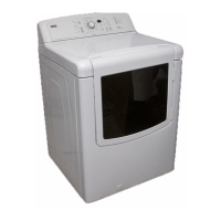
8. Check the belt switch by measuring re-
sistance between the two blue wires, as
shown in Figure 8, while pushing up the
belt switch pulley.
If the resistance reading goes from in
-
finity to a few ohms as pulley arm clos
-
es the switch, belt switch is OK. If not,
replace the belt switch.
If belt switch is OK and there is still an
open circuit, check and repair the wir-
ing harness.
9. Door switch problems can be uncovered
in the Door Switch Diagnostic Test; how
-
ever, if this was not done, the following
can be done without applying power to
the dryer. Connect an ohmmeter across
P8-3 (neutral, white wire) and P8-4 (door,
tan wire).
With the door properly closed, the ohm-
meter should indicate a closed circuit
(0–2 ohms).
If not, replace the door switch assem
-
bly. See Figure 12; and Removing the
Front Panel/Drum Assembly.
TEST #3b Blower Motor (Dual Motor Model)
1. Access the motor control electronics. See
Accessing & Removing the Electronic As
-
semblies.
2. Visually check the communication har-
ness. See Figure 15. The communication
harness is a three-wire harness that con
-
nects between the two electronic control
assemblies. Make sure it is fully inserted
into both electronic controls.
•
•
•
•
2
6
4
3
5
1
Belt Switch
Tension
Pulley
Blue Wires
(Back and 4 position)
Figure 8. Checking the belt switch.
3. If the communication harness looks OK,
go to step 4.
4. Visually check the wire harnesses con-
nected to the motor control electronic
assembly. Make sure they are clean and
fully inserted into the control.
If the connections look OK, go to step 5.
5. Remove the MC2 blower motor electrical
connector from the blower motor elec
-
tronic control.
6. Measure the resistance between the fol-
lowing terminals on the connector: pins
1 to 3, 1 to 5 and 3 to 5. The resistance
should be between 55 and 65 ohms.
If the resistance looks OK, go to step 7.
If the resistance is much greater than
65 ohms, go to step 7.
If the resistance is much less than 55
ohms, replace the blower motor.
7. Visually check the wire harness connec-
tion at the blower motor (See Accessing
the Blower Motor below).
If the connections look OK, check for
obstructions in the blower housing.
Make sure blower fan rotates freely.
If no obstructions are found, replace
the motor control electronic assembly.
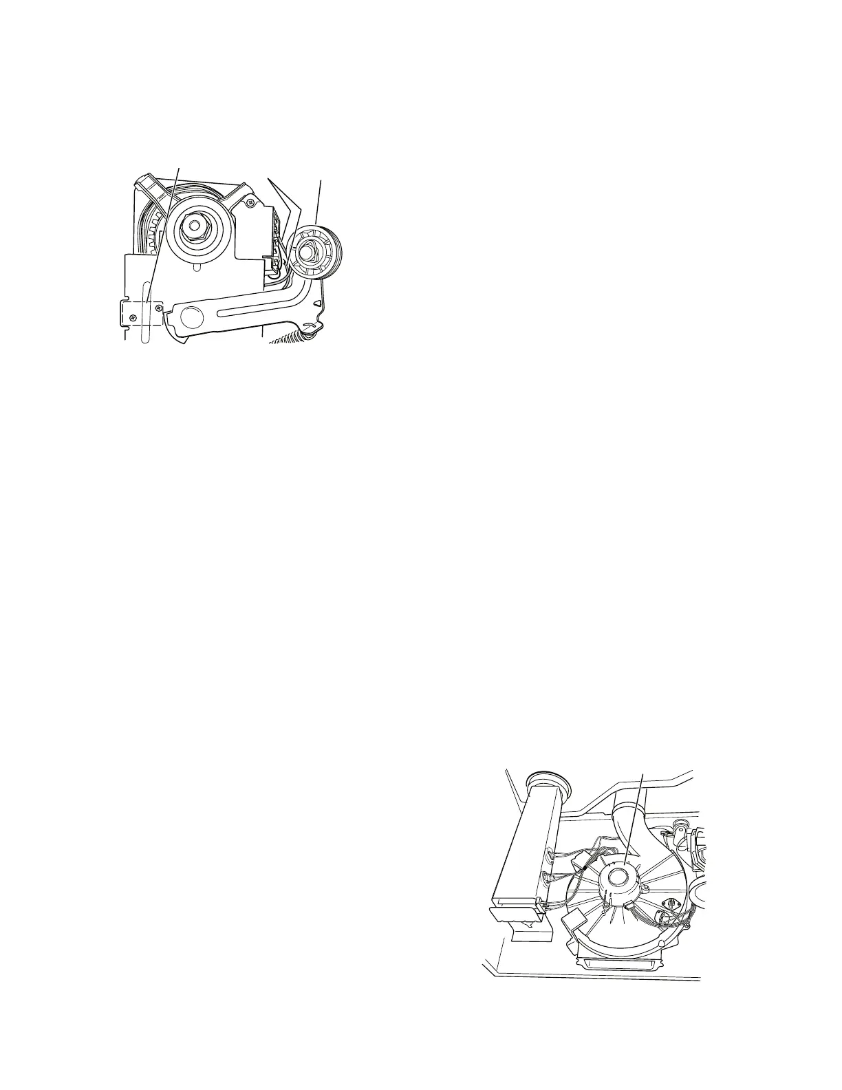
Accessing the Blower Motor:
Follow the steps under Removing the Front
Panel/Drum Assembly. The blower motor is
located on top of the blower housing as shown
in Figure 9.
•
•
•
•
•
•
Blower Motor
Figure 9. Blower motor location.
 Loading...