6-11
If wire connections are good, remove
the two wires from the thermistor and
replace the thermistor. See Figure 10.
Plug in dryer or reconnect power.
4. If
F-22 or F-23 does not flash in the dis-
play, the connections to the thermistor
are good. Therefore, check the exhaust
temperature value at any or all of the
temperature levels in question, using the
Timed Dry cycle, and the following pro
-
cess:
Hold a glass bulb thermometer capable of
reading from 90° to 180°F (32
° to 82°C)
in the center of the exhaust outlet. The
correct exhaust temperatures are as fol
-
lows:
•
•
5. If the exhaust temperature is not within
specified limits, remove the P4 connec
-
tor, then measure the resistance between
P4-3 (red wire) and P4-6 (red wire) at the
connector. See figure 16, for connector
location; and Accessing & Removing the
Electronic Assemblies.
NOTE: All thermistor resistance mea-
surements must be made while dryer is
disconnected from power.
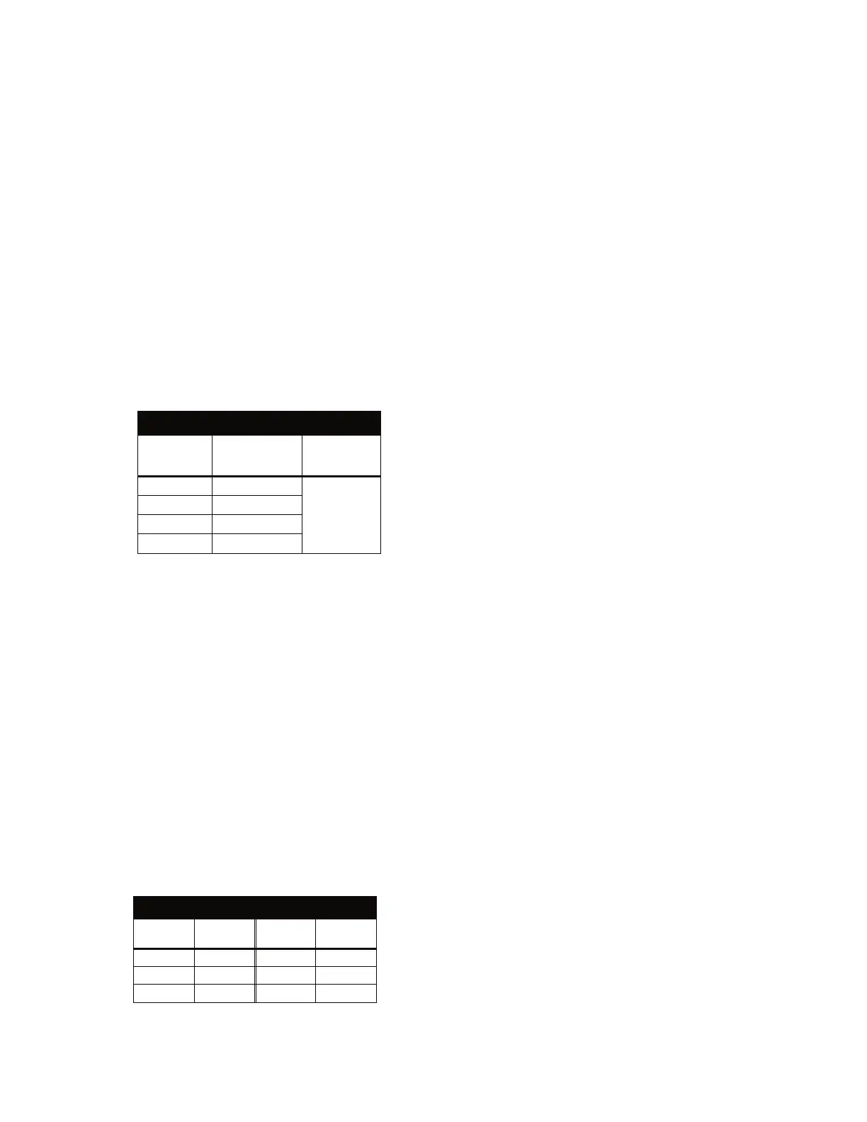
The following table gives temperatures
and ranges for the associated thermistor
resistance values.
EXHAUST TEMPERATURES
TEMPERATURE
SETTING
HEAT TURNS
OFF*
°F (°C)
HEAT TURN
S
ON
°F (°C)
High
155°±5° (68°±3°)
10°–15° (6°–8°)
below the
heat turn of
f
temperatur
e
Medium
140°±5° (60°±3°)
Low
125°±5° (52°±3°)
Extra Low
105°±5° (41°±3°)
* The measured overshoot using the glass
bulb thermometer in the exhaust outlet
can be 30°F (17°C) higher.
If the thermistor resistance does not
agree with table, replace the exhaust
thermistor.
If the thermistor resistance checks
agree with the measurements in the
table, replace the machine control
electronics.
INLET THERMISTOR
The machine control electronics monitors the
inlet temperature using an inlet thermistor that
is part of the high limit thermostat assembly.
1. Activate the diagnostic test mode.
2. If F-24 or F-25 is a displayed error in the
diagnostic test mode, the thermistor or
wire harness is either open or shorted.
Unplug dryer or disconnect power.
Check wire connections at the machine
control electronics and inlet thermistor.
See Accessing & Removing the Elec
-
tronics Assemblies, and for inlet therm
-
istor location see Figure 10.
If wire connections are good, remove
the wires from the inlet thermistor/high
limit thermostat assembly and replace
the assembly.
Plug in dryer or reconnect power.
3. If
F-24 or F-25 is not an error that is dis-
played in the diagnostic test mode, the
connections to the thermistor are good.
Therefore, check the thermistor’s resis-
tance value, using the following process:
Unplug dryer or disconnect power.
Access the heater assembly. See Fig
-
ure 1, and Removing the Front Panel/
Drum Assembly.
Hold a glass bulb thermometer capa
-
ble of reading from 68
° to 176°F (20°
to 80°C) in the heater assembly.
•
•
•
•
•
•
•
•
•
EXHAUST THERMISTOR RESISTANCE
TEMP.
°F (°C)
RES.
k Ω
TEMP.
°F (°C)
RES.
k Ω
50°(10°) 19.0–22.0 80°(27°) 8.5–10.5
60°(16°) 14.8–16.8 90°(32°) 6.8–8.8
70°(21°) 11.5–13.5 100°(38°) 5.0–7.0
 Loading...