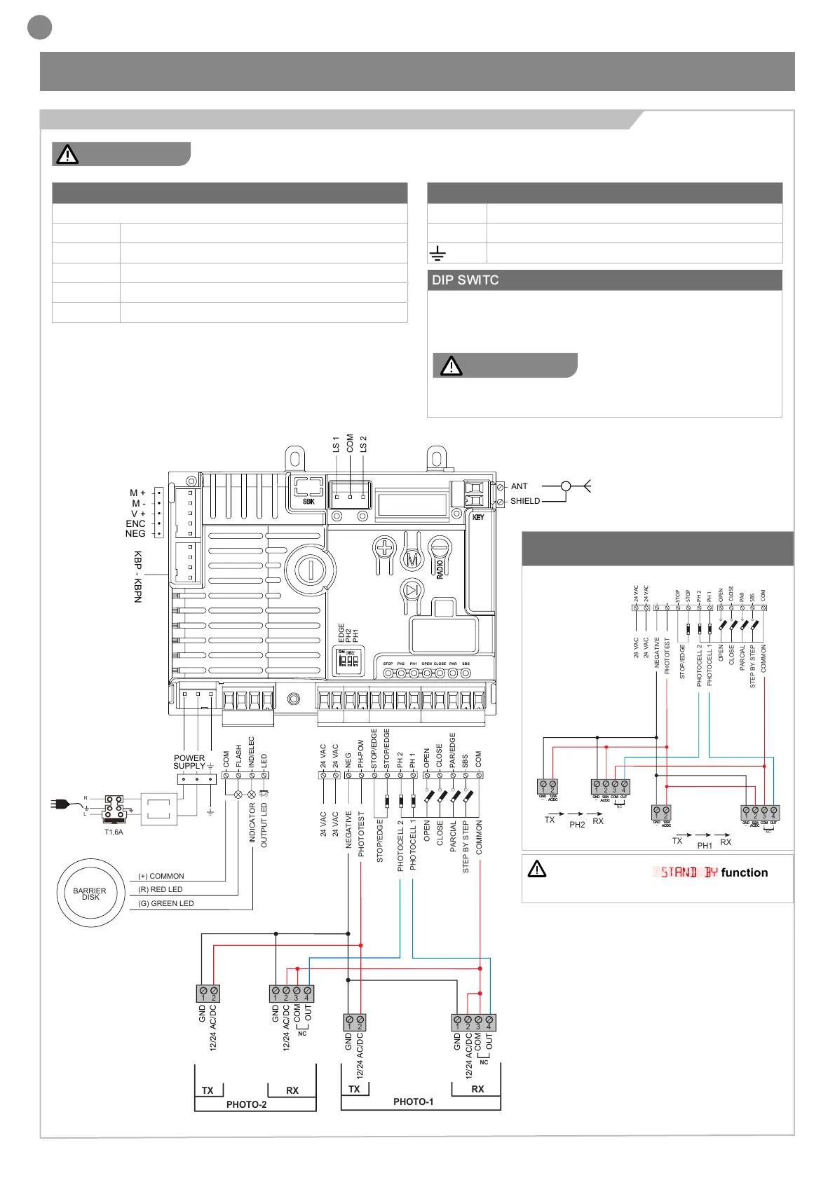
ATTENTION! If the
STAND BY
function is
enabled, the phototest won’t work
22
EN
4 - PRODUCT INSTALLATION
Before making the connections, ensure that the control unit is not powered up.
MOTOR CONNECTOR
Power supply connection terminal board
M + Power supply motor
M - Power supply motor
V + Power supply encoder
ENC Encoder signal
NEG Negative power supply for encoder
POWER SUPPLY CONNECTOR
L Power supply live 230 Vac (110 Vac) 50-60 Hz
N Power supply neutral 230 Vac (110 Vac) 50-60 Hz
Earth
ELECTRICAL CONNECTIONS
FOR ENERGY SAVING
NEG
PH-POW
STOP
STOP
PH 2
COM
FLASH
IND
LED
24 VAC
24 VAC
PH 1
OPEN
CLOSE
SBS
PAR
COM
PHOTOTEST
OUTPUT LED
OPEN
PHOTOCELL 1
PHOTOCELL 2
CLOSE
PARCIAL
STEP BY STEP
COMMON
STOP/EDGE
INDICATOR
NEGATIVE
24 VAC
24 VAC
2
3
4
1
1
2
TX
RX
NC
PH2
2
3
4
1
1
2
TX
RX
PH1
GND
_
12/24
AC/DC
GND
_
12/24
AC/DC
COM
OUT
GND
_
12/24
AC/DC
GND
_
12/24
AC/DC
COM
OUT
NC
POWER
POWER SUPPLY
SUPPLY
N
T1,6A
L
230Vac
50/60Hz
COM
LED
FLASH
STOP
STOP
PH2
PH1
OPEN
CLOSE
PAR
SBS
PH2
PH1
SHIELD
UP
MENU
SBS
DOWN
(RADIO)
ANT
NEG
ENC
V +
M -
M +
BATTERY
LS 1
LS 2
KEY
COM
NEG
PH-POW
STOP/EDGE
STOP/EDGE
PH 2
COM
FLASH
IND/ELEC
LED
24 VAC
24 VAC
PH 1
OPEN
CLOSE
SBS
PAR/EDGE
COM
PHOTOTEST
OUTPUT LED
OPEN
PHOTOCELL 1
PHOTOCELL 2
CLOSE
PARCIAL
STEP BY STEP
COMMON
STOP/EDGE
INDICATOR
NEGATIVE
24 VAC
24 VAC
POWER
SUPPLY
N
T1,6A
L
STOP PH2 PH1 OPEN CLOSE PAR SBS
EDGE
PH2
PH1
ON
SHIELD
ANT
LS 1
LS 2
COM
KBP - KBPN
NEG
ENC
V +
M -
M +
(+) COMMON
(R) RED LED
(G) GREEN LED
BARRIER
DISK
2
3
4
1
1
2
2
3
4
1
1
2
TX RX
PHOTO-1
NC
GND
12/24 AC/DC
GND
12/24 AC/DC
COM
OUT
NC
COM
OUT
GND
12/24 AC/DC
GND
12/24 AC/DC
TX RX
PHOTO-2
DIP SWITCH
This procedure avoids to bridge the terminal board inputs.
If the relative switch is in “ON” the relative input (EDGE, PH1 or
PH2) is disabled
ATTENTION !
with the dip switch ON, the safety
devices are disabled.
To disable, follow the procedure at par. 4.2
4.1 - Electrical connections
ATTENTION !
 Loading...