28
EN
Once all (and not just some) of the system devices have passed the
testing procedure, the system can be commissioned;
the system’s technical dossier must be produced and kept for 10
years. It must contain the electrical wiring diagram, a drawing or
photograph of the system, the analysis of the risks and the solutions
adopted to deal with them, the manufacturer’s declaration of con-
formity for all connected devices, the operator’s manual for every
device and the system maintenance plan;
x a dataplate with the details of the automation, the name of the
person who commissioned it, the serial number and year of con-
struction and the CE marking on the gate or door;
also t a sign specifying the procedure for releasing the system by
hand;
draw up the declaration of conformity, the instructions and precau-
tions for use for the end user and the system maintenance plan and
consign them to the end user;
ensure that the user has fully understood how to operate the system
in automatic, manual and emergency modes;
the end user must also be informed in writing about any risks and
hazards still present;
ATTENTION !
After detecting an obstacle, the gate or door stops during its
opening travel and automatic closure is disabled; to restart
operation, the user must press the control button or use the
transmitter.
5 - TESTING AND COMMISSIONING THE AUTOMATION SYSTEM
All system components must be tested following the procedures de-
scribed in their respective operator’s manuals;
ensure that the recommendations in Chapter 1 - Safety Warnings -
have been complied with;
check that the gate or door is able to move freely once the automa-
tion system has been released and is well balanced, meaning that it
will remain stationery when released in any position;
check that all connected devices (photocells, sensitive edges, emer-
gency buttons, etc.) are operating correctly by performing gate or
door opening, closing and stop tests using the connected control
devices (transmitters, buttons or switches);
perform the impact measurements as required by the EN 12453,stan-
dard, adjusting the control unit’s speed, motor force and decelera-
tion functions if the measurements do not give the required results,
until the correct setting is obtained.
The system must be tested by a qualied technician, who must per-
form the tests required by the relevant standards in relation to the
risks present, to check that the installation complies with the relevant
regulatory requirements, especially the EN 12453, standard which
species the test methods for gate and door automation systems.
6 - FURTHER DETAILS - ADVANCED MENU
The ADVANCED MENU allows the system to be further customised
by modifying parameters not accessible from the basic menu.
To access the ADVANCED menu, press the MENU key and hold
it down for 5 seconds.
* For TUS4324 and SUN5324 max= 2
** For TUS4324 and SUN5324 max = 15
To modify ADVANCED MENU parameters, proceed as described
for the BASIC MENU.
N.B. Some default functions/display items may vary with respect to
the type of motor selected.
5.1 Testing
5.2 Commissioning
10
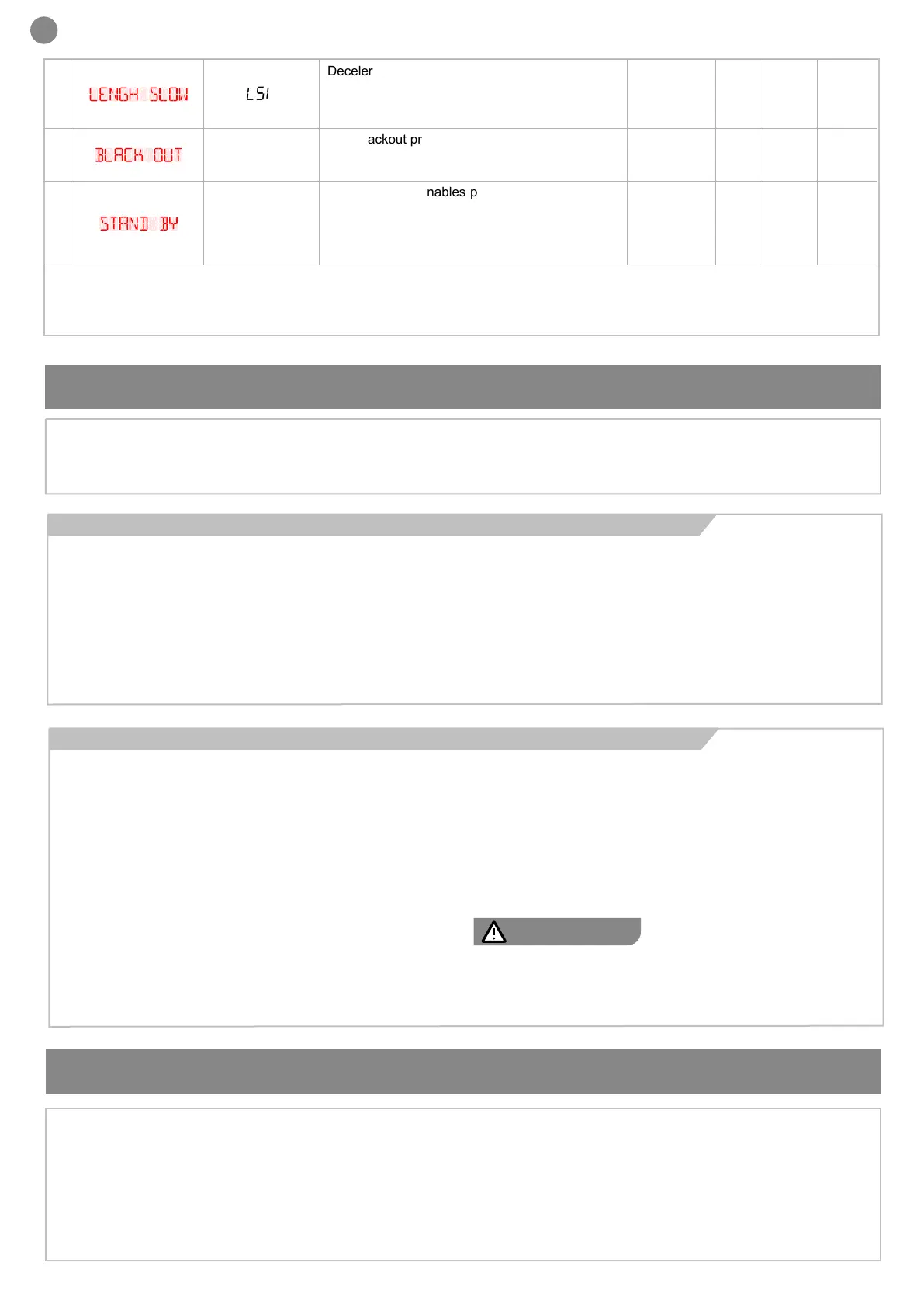
lengh slow
LSI
Deceleration distance
1 to 100 = Motor deceleration percentage during
opening and closure
P= customized decelerations
20 1** 100 %
11
black out
BlT
Post blackout procedure
0 = No action, remains stationery
1 = Closure
0 0 1
12
stand by
SBY
Energy saving: enables photocell switch-o when
gate is closed (only during this function PHOTO-
TEST is not possible)
0= disabled
1= enabled
0 0 1
 Loading...