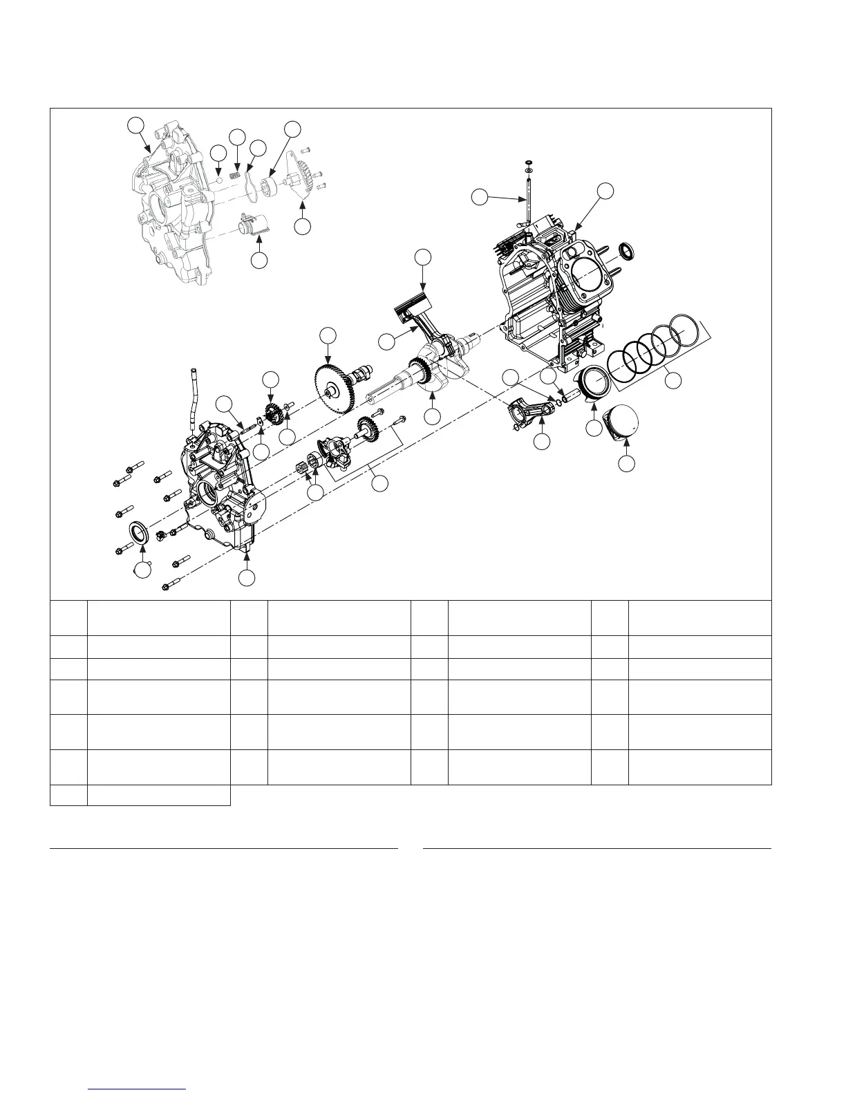
Crankcase Components
A
B
H
F
K
G
L
J
C
D
E
J
I
L
M
N
P
O
Q
X
W
S
T
V
U
R
A Closure Plate Seal B
Closure Plate
(Style A)
C
Gerotor Gears
(Style A)
D
Oil Pump Assembly
(Style A)
E Governor Shaft F Governor Washer G Governor Gear H Governor Cup
I Camshaft J Connecting Rod K Crankshaft L Piston (Style B)
M Piston Pin N
Piston Pin Retainer
Clip
O Crankcase P
Governor Cross
Shaft
Q Piston Rings R
Closure Plate
(Style B)
S Ball (Style B) T Spring (Style B)
U
Oil Pump Cover
O-ring (Style B)
V
Outer Gerotor Gear
(Style B)
W
Oil Pump Assembly
(Style B)
X
Oil Pick-Up Tube
(Style B)
Y Piston (Style A)
Remove Camshaft
Remove camshaft.
Inspection and Service
NOTE: To prevent repeat failures, camshaft and
crankshaft should always be replaced as a set.
Check lobes of camshaft for wear or damage. See
Specifi cations for minimum lift tolerances. Measurement
must be performed while valve train is still assembled.
Inspect cam gear for badly worn, chipped or missing
teeth. Replacement of camshaft will be necessary if any
of these conditions exist.
Remove Governor Cross Shaft
1. Remove retainer and nylon washer, from governor
cross shaft.
2. Remove cross shaft through inside of crankcase.
Y
Disassembly/Inspection and Service
116 24 690 01 Rev. KKohlerEngines.com
 Loading...