2. To assist assembly, fi nd 4 intake manifold studs with
M6 thread at least 100 mm in length to be used as
guide pins. Insert intake manifold studs through
cooling fan mounting holes and thread them 4 or 5
turns into fl ywheel.
3. Install a spring washer on each stud with concave
side down toward cooling fan.
4. Install a spacer on each stud with stepped end
down. Smaller diameter should extend through
spring washer and fan, so tip is resting on fl ywheel,
and shoulder is resting on spring washer.
5. Install support ring on studs, so it is resting on
spacers. Then install metal screen on top of support
ring.
6. Install plain washers on each hex cap screw. Apply
Loctite
®
242
®
to hex cap screw threads.
7. Carefully remove 2 studs and replace with 2 screws.
Torque screws to 9.9 N·m (88 in. lb.). Repeat
procedure for other 2 studs and screws.
Install Plastic Debris Screen
Place plastic grass screen on fan and secure with hex
screws. Torque screws to 4.0 N·m (35 in. lb.).
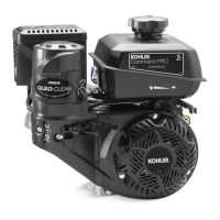
Install Electric Starter Motor and ECU Bracket (ECH
EFI)
1. Install electric starter motor using screws. Position
ECU bracket as shown.
2. Torque screws to 16.0 N·m (142 in. lb.).
3. Connect leads to solenoid.
ECU (ECH EFI)
Install Electronic Control Unit (ECU)
B
A
C
A
Electronic Control
Unit (ECU)
B ECU Bracket
C Starter
NOTE: ECU pins should be coated with a thin layer of
electrical grease to prevent fretting and
corrosion and may need to be reapplied if ECU
is being reused.
1. Install ECU to ECU bracket using screws. Torque
M5 screws to 6.2 N·m (55 in. lb.) into new holes or
4.0 N·m (35 in. lb.) into used holes.
2. Connect Black and Grey electrical connectors.
Connectors and ECU are keyed in such a way so
they cannot be installed incorrectly.
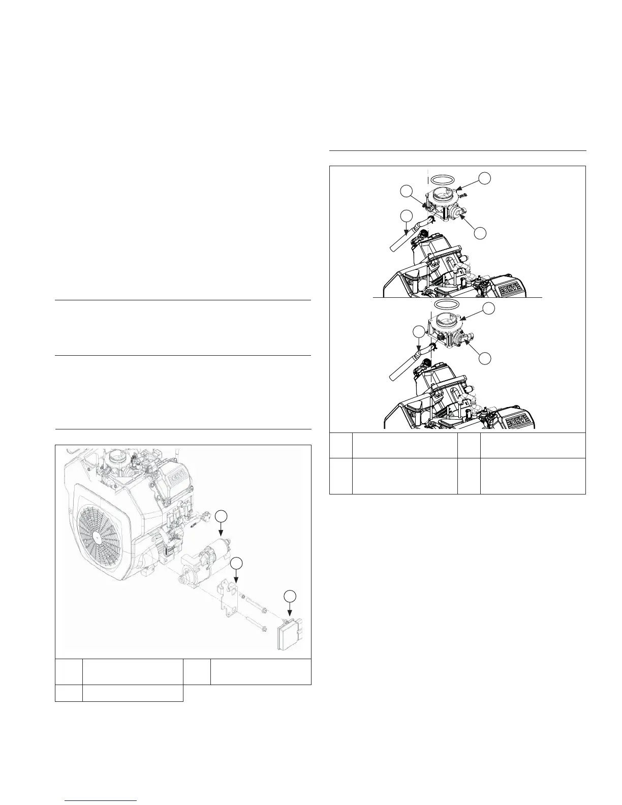
Install Throttle Body (ECH EFI)
Throttle Body Components (ECH EFI)
A
C
D
A
B
B
D
A Throttle Body B
Throttle Position
Sensor (TPS)
C
Intake Air
Temperature
(IAT) Sensor
D Breather Tube
NOTE: Ensure all parts are clean, undamaged and free
of debris and make sure electrical connector
has seal in place.
NOTE: Earlier engines have separate IAT and MAP
sensors.
1. Install a new throttle body O-ring prior to installation.
Make sure all holes align and are open.
2. Install throttle body, throttle position sensor, intake
air temperature (IAT) sensor (earlier engines only),
throttle linkage, spring and bushing, as an assembly.
3. Install air cleaner bracket (models with heavy-duty
air cleaner only) to valve covers. Torque screws to
9.9 N·m (88 in. lb.).
4. On earlier engines with separate intake air
temperature (IAT) and MAP sensor, push electrical
connector onto IAT sensor making sure a good
connection is made by listening for a click.
5. Connect breather hose to throttle body using a pliers
to compress spring clamp. Route hose around
throttle body and connect to breather cover using a
spring clamp.
Reassembly
13324 690 01 Rev. K KohlerEngines.com
 Loading...