Install Hydraulic Lifters
NOTE: Hydraulic lifters should always be installed in same position as before disassembly. Exhaust lifters are located
on output shaft side of engine while intake lifters are located on fan side of engine. Cylinder numbers are
embossed on top of crankcase and each cylinder head.
1. See Servicing Hydraulic Lifters in Disassembly/Inspection and Service.
2. Apply camshaft lubricant to bottom surface of each lifter. Lubricate hydraulic lifters and lifter bores in crankcase
with engine oil.
3. Note mark or tag identifying hydraulic lifters as either intake or exhaust and cylinder 1 or cylinder 2. Install
hydraulic lifters into their appropriate location in crankcase. Do not use a magnet.
4. If breather reeds and stops were removed from crankcase, reinstall them at this time and secure with screw.
Torque screw to 4.0 N·m (35 in. lb.).
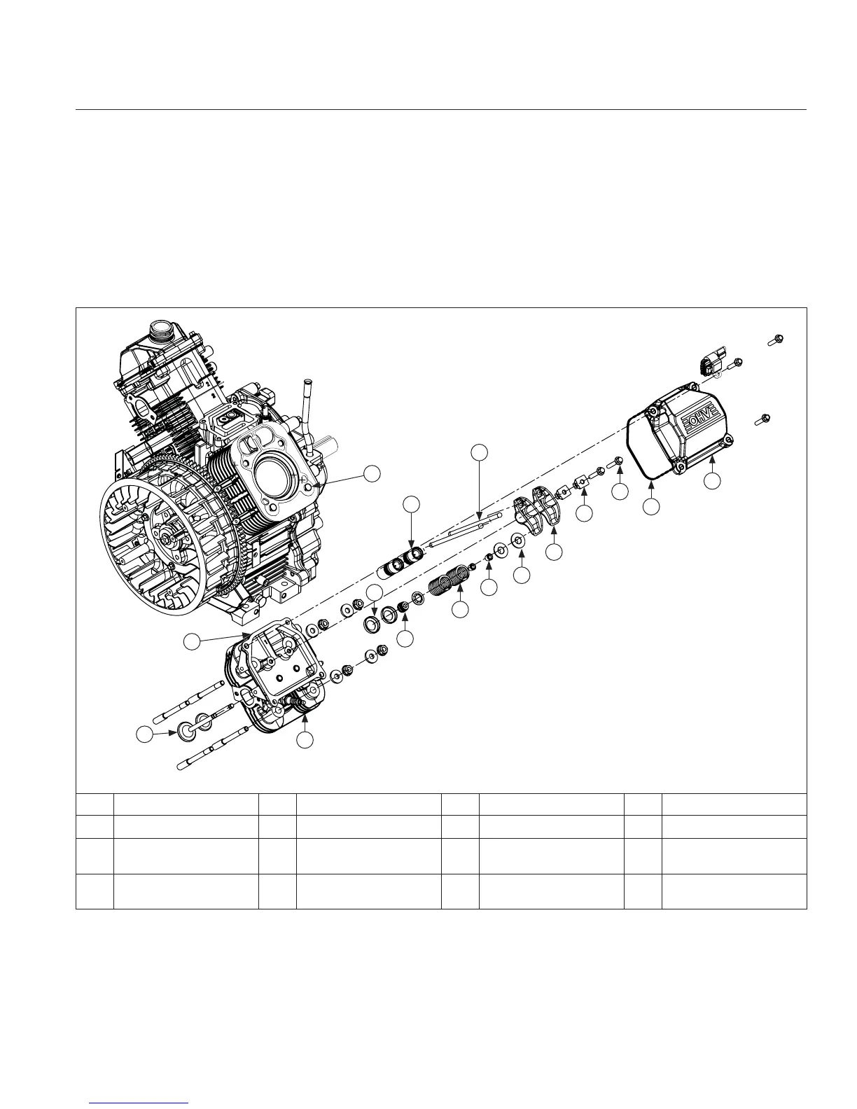
Cylinder Head Components
A
B
C
D
H
I
L
G
F
J
M
K
N
O
P
E
A Valve Cover B Valve Cover Gasket C Hex Flange Screw D Rocker Arm Pivot
E Rocker Arm F Push Rod G Hydraulic Lifter H Valve Cap
I Valve Keeper J Valve Spring K Valve Seal L
Valve Spring
Retainer
M Cylinder Head N
Cylinder Head
Gasket
O Valve P Dowel Pin
Reassembly
12724 690 01 Rev. K KohlerEngines.com
 Loading...