7124 690 01 Rev. K KohlerEngines.com
EFI SYSTEM-BOSCH
Internal (In-Tank) Regulator-
Remove screws securing retaining ring and
regulator in base/holder assembly. Grasp and pull
regulator out of base/holder.
5. Always use new O-Rings and hose clamps when
installing a regulator. A new replacement regulator
will have new O-Rings already installed. Lubricate
O-Rings (external regulator) with light grease or oil.
6. Install new regulator by carefully pushing and
rotating it slightly into base or housing.
a. External Regulators with Square Base Housing
Only; Install a new O-Ring between regulator and
mounting bracket. Set mounting bracket into
position.
b. Secure the regulator in base with original
retaining ring or screws. Be careful not to dent or
damage body of regulator as operating
performance can be affected.
7. Reassemble and connect any parts removed in step
3.
8. Reconnect negative (-) battery cable.
9. Recheck regulated system pressure at fuel rail test
valve.
Fuel Rail
Fuel rail is mounted to throttle body/intake manifold. No
specifi c servicing is required unless operating conditions
indicate that it needs internal cleaning or replacement.
It can be detached by removing mounting screws and
injector retaining clips. Thoroughly clean area around
all joints and relieve any pressure before starting any
disassembly.
Throttle Body/Intake Manifold Assembly
Throttle body/intake manifold is serviced as an
assembly, with throttle shaft, TPS, throttle plates,
and idle speed adjusting screw installed. Throttle
shaft rotates on needle bearings (non-serviceable),
capped with rubber seals to prevent air leaks. A throttle
shaft repair kit is available to replace shaft if worn or
damaged. Appropriate TPS Initialization Procedure must
be performed after any throttle shaft service.
Idle Speed Adjustment (RPM)
Adjustment Procedure
1. Make sure there are no fault codes present in ECU
memory.
2. Start engine and allow it to fully warm up and
establish closed looped operation (approximately
5-10 min.).
3. Place throttle control in IDLE/SLOW position and
check idle speed with a tachometer. Turn idle speed
screw in or out as required to obtain 1500 RPM, or
idle speed specifi ed by equipment manufacturer.
4. Idle speed adjustment can affect high idle speed
setting. Move throttle control to full throttle position
and check high idle speed. Adjust as necessary to
3750 RPM, or speed specifi ed by equipment
manufacturer.
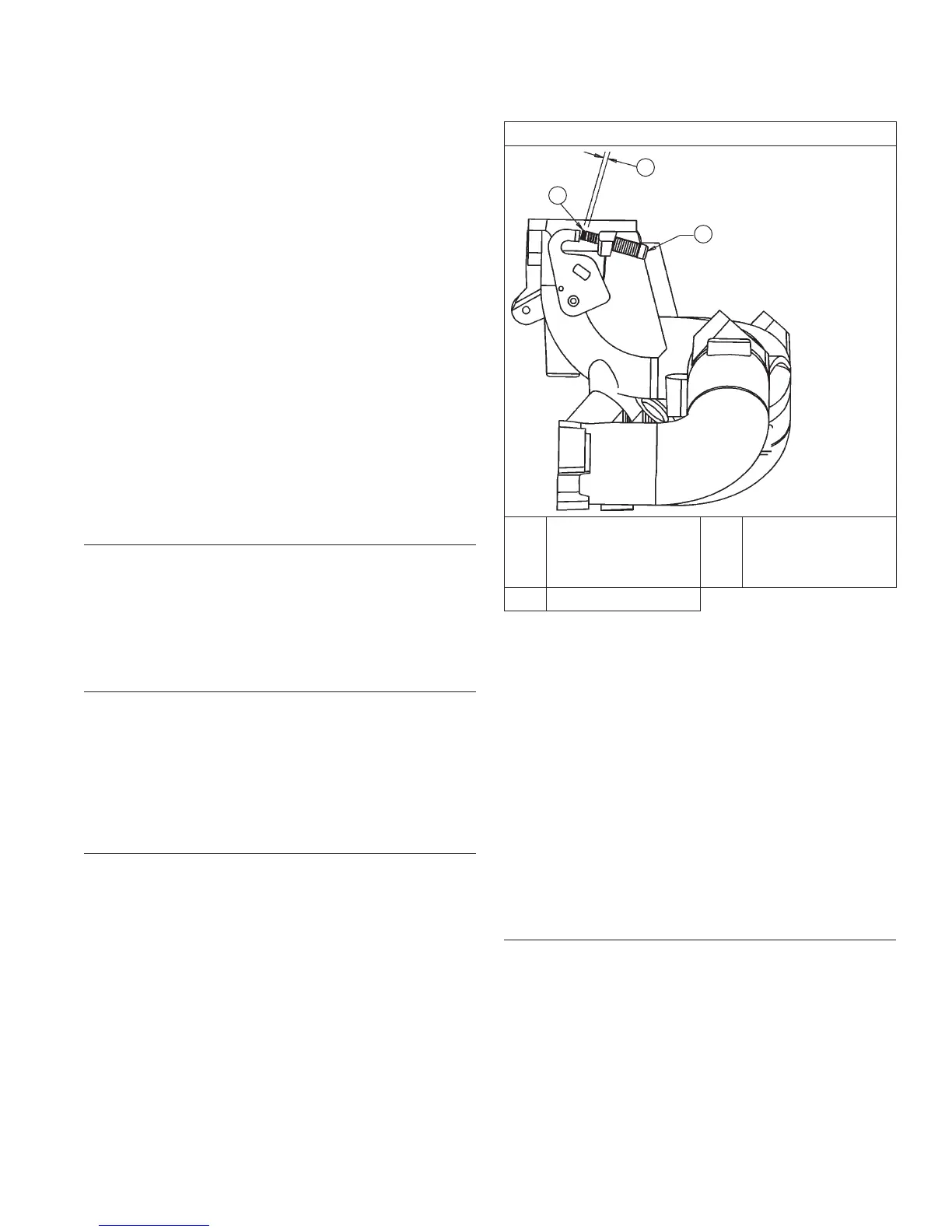
Idle Speed Screw Dampening Spring
Idle Speed Screw Details
C
B
A
A
Dampening Spring
(Some Models)
B
1-3 mm (0.039-
0.117 in.) Exposed
Length Off End Of
Adjustment Screw
C Idle Speed Screw
A small dampening spring is attached to end of idle
speed screw of some EFI engines to help stabilize no
load operating speeds.
Idle speed adjustment procedure remains same for
engines with or without a dampening spring. Typically, no
periodic servicing is necessary in this area. If however,
removal/replacement of dampening spring is required,
reinstall it as follows:
1. Thread spring onto end of idle screw leaving 1-3 mm
(0.039-0.117 in.) of spring extending beyond end of
idle speed screw.
2. Secure spring onto screw with a small amount of
Permabond
™
LM-737 or equivalent Loctite
®
adhesive. Do not get any adhesive on free coils of
spring.
3. Start engine and recheck idle speed settings, after
suffi cient warm up. Readjust as required.
Initial Governor Adjustment
Initial governor adjustment is especially critical on
EFI engines because of accuracy and sensitivity of
electronic control system. Incorrect adjustment can
result in overspeed, loss of power, lack of response, or
inadequate load compensation. If you encounter any
of these symptoms and suspect them to be related to
governor setting, following should be used to check and/
or adjust governor and throttle linkage.
 Loading...