Install Fuel Pump
WARNING
Explosive Fuel can cause res and severe
burns.
Do not ll fuel tank while engine is hot or
running.
Gasoline is extremely ammable and its vapors can
explode if ignited. Store gasoline only in approved
containers, in well ventilated, unoccupied buildings,
away from sparks or ames. Spilled fuel could ignite
if it comes in contact with hot parts or sparks from
ignition. Never use gasoline as a cleaning agent.
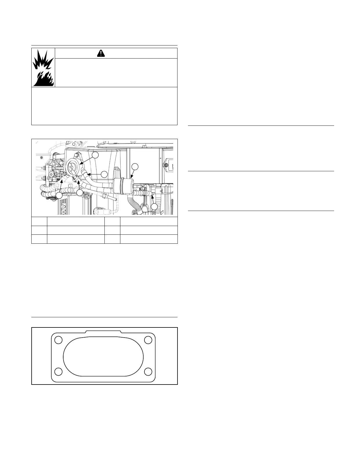
Fuel Pump Components
B
A
D
C
E
F
A Outlet Fuel Line B Pulse Line
C Crankcase Fitting D Inlet Fuel Line
E Fuel Filter F Fuel Pump
NOTE: If a new fuel pump is being installed, make sure
orientation of new pump is consistent with
removed pump. Internal damage may occur if
installed incorrectly.
1. Install fuel pump and lines as an assembly. Connect
pulse line to crankcase vacuum tting.
2. Install fuel pump using screws. Torque screws to 2.3
N·m (20 in. lb.).
3. Connect fuel lines.
Install Air Cleaner Assembly
Torque Sequence
1, 5
4, 8
3, 7
2, 6
1. Install a new air cleaner gasket. Make sure all holes
align and are open.
2. Some engines have an evap connector tting on the
air cleaner housing. If this was removed, secure
tting to housing with hi-lo screw. Torque screw to
2.1 N·m (19 in. lb.).
3. Install air cleaner assembly and any clips onto
mounting studs. Secure with hex ange nuts. Torque
nuts in 2 stages: rst to 7.3 N·m (65 in. lb.), then
nally to 8.2 N·m (73 in. lb.), using sequence shown.
4. Install 2 screws securing support bracket to air
cleaner assembly. Torque screws to 7.9 N·m
(70 in. lb.).
5. Connect breather hose to air cleaner.
Install Mufer
1. Install port liners (if equipped). Install mufer and
attaching hardware to mufer bracket. Torque
screws to 9.9 N·m (88 in. lb.).
2. Install hex ange nuts to exhaust studs. Torque nuts
to 24.4. N·m (216 in. lb.).
Install Oil Cooler (if equipped)
1. Secure adapter to oil pan with oil lter nipple. Torque
oil lter nipple to 27 N·m (20 ft. lb.).
2. Install screws and secure oil cooler to blower
housing.
Install Oil Filter and Fill Crankcase with Oil
NOTE: Make sure that both oil drain plugs are installed
and torqued to specications to prevent oil
leakage.
1. Install oil drain plug(s). Torque plug(s) to 13.6 N·m
(10 ft. lb.). If oil drain valve is used, make sure valve
body is closed and cap is on.
2. Place new lter in shallow pan with open end up. Fill
with new oil until oil reaches bottom of threads. Allow
2 minutes for oil to be absorbed by lter material.
3. Apply a thin lm of clean oil to rubber gasket on oil
lter.
4. Refer to instructions on oil lter for proper
installation.
5. Fill crankcase with new oil. Level should be at top of
indicator on dipstick.
6. Reinstall oil ll cap/dipstick and tighten securely.
Reassembly
6524 690 37 Rev. B KohlerEngines.com
 Loading...