TP-7070 8/2044 Section 2 Operation
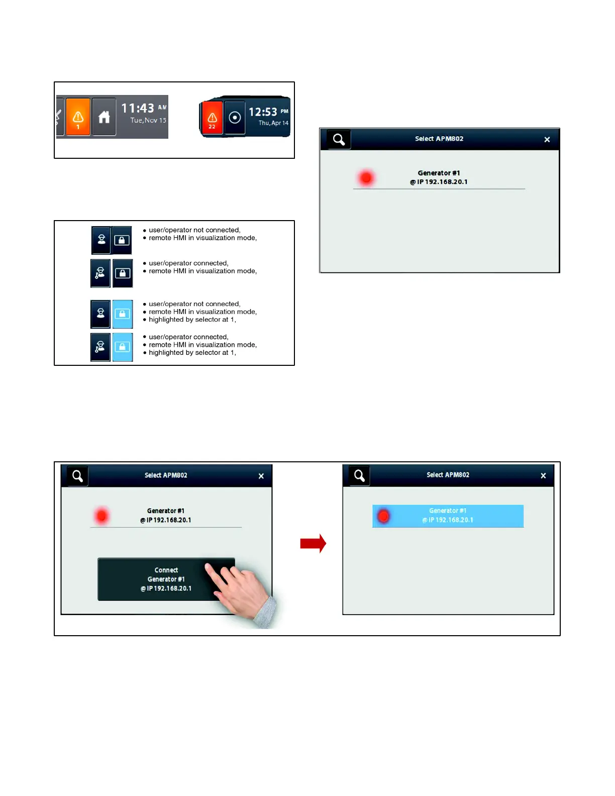
The Home button on the Remote HMI looks different
t
han the Home button on the local HMI. See
Figure 2-44.
Local HMI Remote HMI
Figure 2-44 Home Buttons
In the case of a Remote HMI in Visualization mode, the
icons in Figure 2-45 show the various displays of key 2.
Figure 2-45 Remote HMI Indication
In the case of a Remote HMI in Operation mode or in Full
access mode, button 2 does not change appearance.
A remote HMI is connected to the Ethernet ring. When
the Home button is pressed, a pop- up window appears;
the search for base modules connected to the ring is in
progress.
At the end of the search, the IP addresses of the
modules connected to the Ethernet ring are shown (see
Figure 2-46). It is also possible to see whether one of the
connected generator sets has a fault (red indicator).
Figure 2-46 IP Address Display
Select the base module to connect to (in the example,
there is only one generator set). A Connect Generator
#1 button also appears.
Press the Connect Generator #1 button. The window
changes as shown in Figure 2-47.
Press the magnifying glass at the top left-hand of the
screen to start a new search to select another module
connected to the Ethernet ring.
Figure 2-47 Selecting a Module from a Remote HMI
 Loading...

