TP-7070 8/20 47Section 2 Operation
2.11.8 Ladder Tools
Ladder is a standardized graphic language which is very
s
imilar to a ladder diagram. Implemented in the base
module of the APM802, it is used to define the PLC
functions required for specific functions.
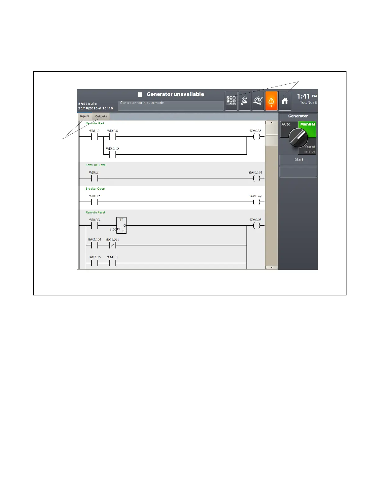
Pressing the Ladder tools icon takes you to the screen
shown in Figure 2-53. See Figure 2-38 for the location
of the Ladder tools icon on the applications screen.
1. Network access keys
2. Press one of these button to exit the ladder screen
1
2
Figure 2-53 Ladder Screen
To exit the Ladder screen, press the Applications button
or the Home button on the top bar.
Generally speaking, there will be at least 2 networks:
The inputs network (accessed via the Inputs key)
The outputs network (accessed via the Outputs key).
Depending on the complexity of the application, there
may be an intermediate network.
The Inputs network defines all the input equations for
the system. These inputs correspond to the physical
inputs for the base module.
The #1 network defines all the intermediate equations
used for the connection between inputs and outputs.
The Outputs network defines all the output equations for
the system. These outputs correspond to the physical
outputs for the base module. See Figure 2-55.
In all networks, press on the contact or the coil to access
more information.
 Loading...

