TP-7070 8/2066 Section 2 Operation
2.12.5 Menus 5 and 6
Except for menu 6.5, communication, menus 5 and 6 are view-only menus that can be seen when logged in as an
o
perator (1966). The view-only menus are not shown in this document.
2.12.6 Menu 6.5-Communication
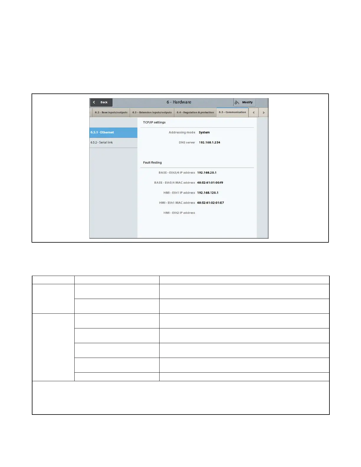
Screen 6.5.1- Ethernet
The 6.5.1Ethernet screen defines the computer addresses for the Ethernet connections for the base module and the
HMI module.
Figure 2-75 Ethernet Screen
The screen is accessible for modification at the operator level, but only for the TCP/IP configuration section.
Group Title Description and Possible Settings
TCP/IP
Settings
Addressing mode * Choice of address type for the TCP/IP connection: System, Customer
IP, or DHCP.
DNS server IP address of the DNS server. The DNS server is used to make the
connection between an APM802 system and an IP address.
Fault Finding Base - Eth3/4 IP address * Permanent or temporary identification number for the base module
connected to another base or to a mains.
Base - Eth3/4 MAC address * Unique permanent physical identification number, which is stored in
the base module.
HMI - Eth1 IP address * Permanent or temporary identification number for the HMI module
connected to another base or to a mains.
HMI - Eth1 MAC address * Unique permanent physical identification number, which is stored in
the HMI module.
HMI - Eth2 IP address Not used.
* IP = Internet Protocol; MAC = Media Access Control.
Eth1 = Ethernet port marked 1 at the rear of the HMI module
Eth3/4 = Ethernet ports marked 3 or 4 on the front of the base module
DHCP: the DHCP protocol (Dynamic Host Configuration Protocol) allows an APM system to connect to a network, which dynamically
assigns it an IP address
Figure 2-76 Ethernet Settings
 Loading...

