10 TUNING THE CHASSIS 36
10.16 Handlebar position
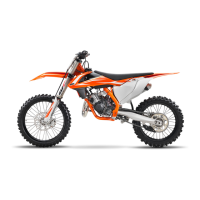
H01188-10
The holes on the handlebar supports are placed at a distance of
A
from the center.
Hole distance A 3.5 mm (0.138 in)
The handlebar can be mounted in 2 different positions. In this way, the handlebar can
be mounted in the most comfortable position for the rider.
10.17 Adjusting the handlebar position
Warning
Danger of accidents A repaired handlebar poses a safety risk.
If the handlebar is bent or straightened, the material becomes fatigued. The handlebar may break as a result.
– Change the handlebar if the handlebar is damaged or bent.
Preparatory work
– Remove the handlebar cushion.
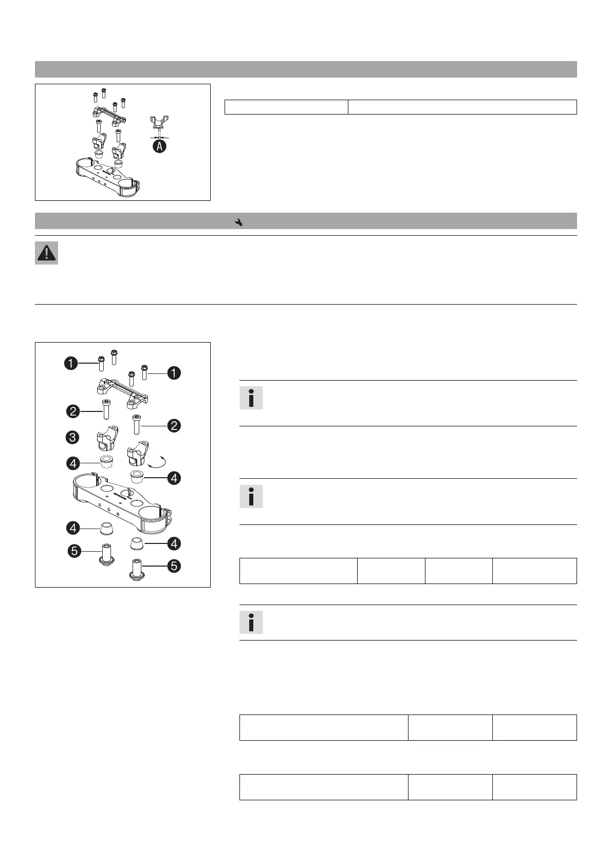
H01189-10
Main work
–
Remove screws
1
. Remove the handlebar clamp. Remove the handlebar and lay it
to one side.
Info
Cover the components to protect them against damage.
Do not kink the cables and lines.
–
Remove screws
2
. Take off handlebar supports
3
.
–
Position rubber bushings
4
and push through nuts
5
from below.
– Place the handlebar supports in the required position.
Info
The handlebar supports are longer and higher on one side.
Position the left and right handlebar supports evenly.
–
Mount and tighten screws
2
.
Guideline
Screw, handlebar support M10 40 Nm
(29.5 lbf ft)
Loctite
®
243™
– Position the handlebar.
Info
Make sure the cables and wiring are positioned correctly.
– Position the handlebar clamp.
–
Mount screws
1
but do not tighten yet.
–
First bolt the handlebar clamp with screws
1
onto the longer, higher side of the
handlebar supports so that both parts touch.
Guideline
Screw, handlebar clamp M8 20 Nm
(14.8 lbf ft)
–
Tighten screws
1
evenly.
Guideline
Screw, handlebar clamp M8 20 Nm
(14.8 lbf ft)
 Loading...