11 SERVICE WORK ON THE CHASSIS 40
11.6 Installing the fork legs
H01182-10
Main work
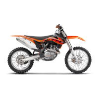
– Position the fork legs.
Bleeder screw
1
of the right fork leg is positioned to the front.
Valve
A
of the left fork leg faces the front.
Info
Grooves are milled into the side of the upper end of the fork legs. The sec-
ond milled groove (from the top) must be flush with the top edge of the
upper triple clamp.
The air suspension is located in the left fork leg. The pressure and rebound
damping is located in the right fork leg.
F00011-11
–
Tighten screws
2
.
Guideline
Screw, top triple clamp M8 17 Nm
(12.5 lbf ft)
–
Tighten screws
3
.
Guideline
Screw, bottom triple clamp M8 12 Nm (8.9 lbf ft)
K00462-11
–
Position the brake caliper. Mount and tighten screws
4
.
Guideline
Screw, front brake caliper M8 25 Nm
(18.4 lbf ft)
Loctite
®
243™
–
Position the brake line and clamp. Mount and tighten screws
5
.
Finishing work
– Install the front wheel. ( p. 71)
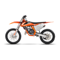
11.7 Removing the fork protector
F00024-10
–
Remove screws
1
. Remove the clamp.
–
Remove screws
2
. Take off the left fork protector.
–
Remove screws
3
. Take off the right fork protector.
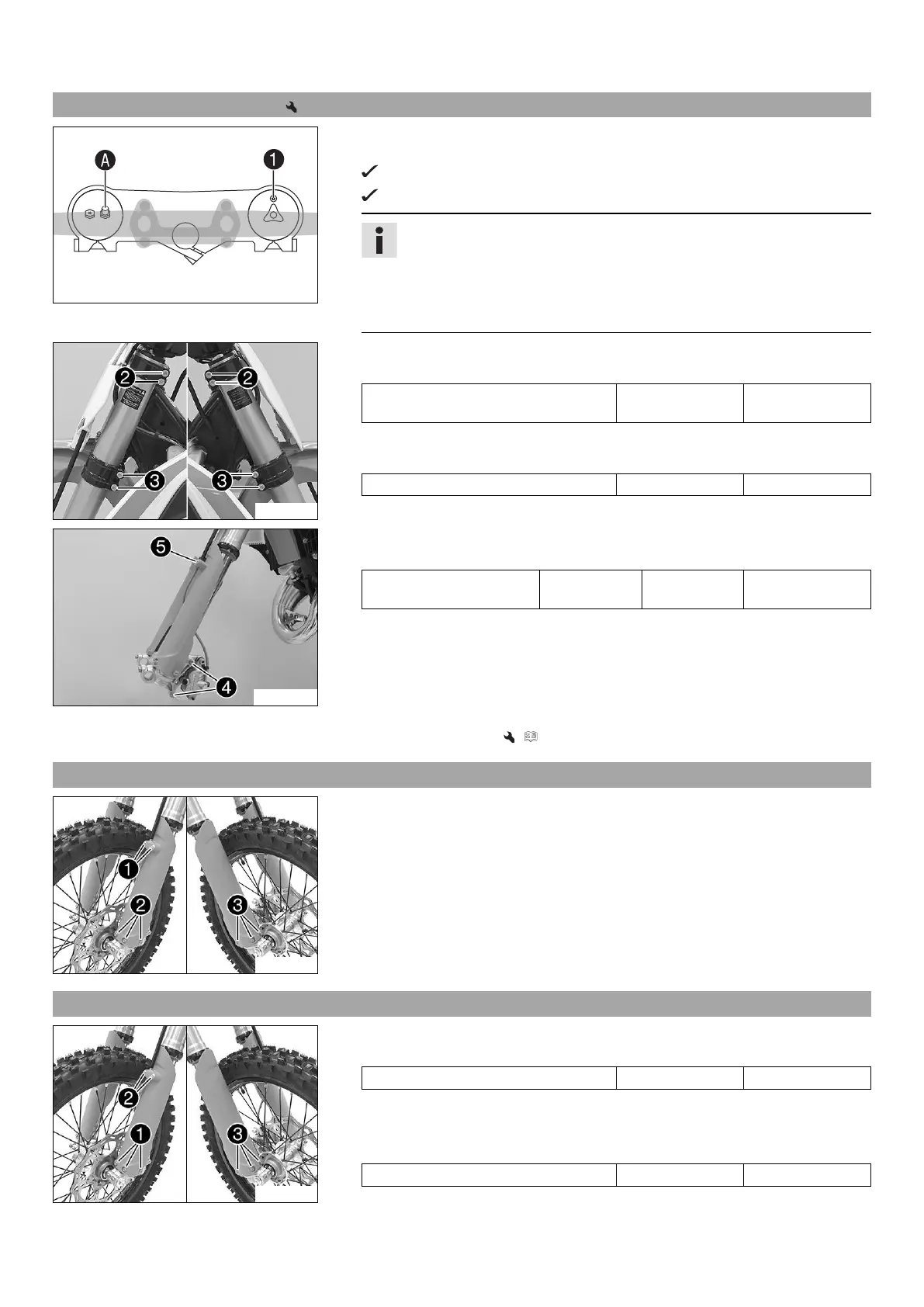
11.8 Installing the fork protector
F00024-11
–
Position the fork protection on the left fork leg. Mount and tighten screws
1
.
Guideline
Remaining screws, chassis M6 10 Nm (7.4 lbf ft)
–
Position the brake line and clamp. Mount and tighten screws
2
.
–
Position the fork protector on the right fork leg. Mount and tighten screws
3
.
Guideline
Remaining screws, chassis M6 10 Nm (7.4 lbf ft)
 Loading...