B1700'B21 00·B2400 WSM, 11770
1
ENGINE
ST10F040
Connecting
Rod
Alignment
III
NOTE
..
Since
the I.D.
of
the connecting rod small end bushing
is
the
basis
of
this check, check the bushing
for
wear beforehand.
1.
Install the piston pin into the connecting rod.
2.
Install the connecting rod on the connecting rod alignment
tool
(Code
No:
07909-31661).
3.
Put a gauge over the piston pin and move
it
against
the
face
plate.
4.
If
the gauge does not
fit
squarely against
the
face plate,
measure the
space
between the pin
of
the gauge and
the
face plate.
5.
If
the measurement
exceeds
the allowable limit, replace
the
connecting rod.
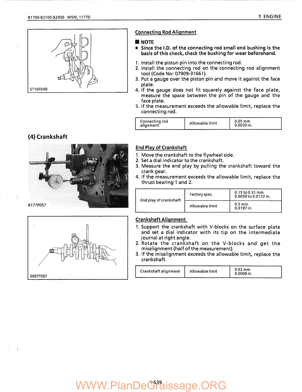
(4) Crankshaft
connecting rod
alignment
Allowable
limit
0.05
mm
0.0020 in.
End
Play
of
Crankshaft
1.
Move the crankshaft
to
the flywheel side.
2.
Set
a dial indicator
to
the crankshaft.
3.
Measure the end play
by
pulling the crankshaft
toward
the
crank gear.
4.
If
the measurement
exceeds
the allowable limit, replace
the
thrust bearing 1and
2.
Factory
spec.
0.15toO.31 mm
0.0059
to
0.0122 in.
End
play
of
crankshaft
Allowable
limit
0.5mm
0.0197 in.
Crankshaft Alignment
1.
Support the crankshaft
with
V-blocks on
the
surface plate
and set a dial indicator
with
its
tip
on
the
intermediate
journal
at
right angle.
2.
Rotate
the
crankshaft
on
the
V-blocks
and
get
the
misalignment (half
ofthe
measurement).
3.
If
the misalignment
exceeds
the allowable limit, replace
the
crankshaft.
0087F067
Crankshaft alignment
1-S39
Allowable
limit
0.02 mm
0.0008 in.
 Loading...