3
TRANSMISSION
(2)-2. Pump and
Motor
81700·82100·82400 WSM,11770
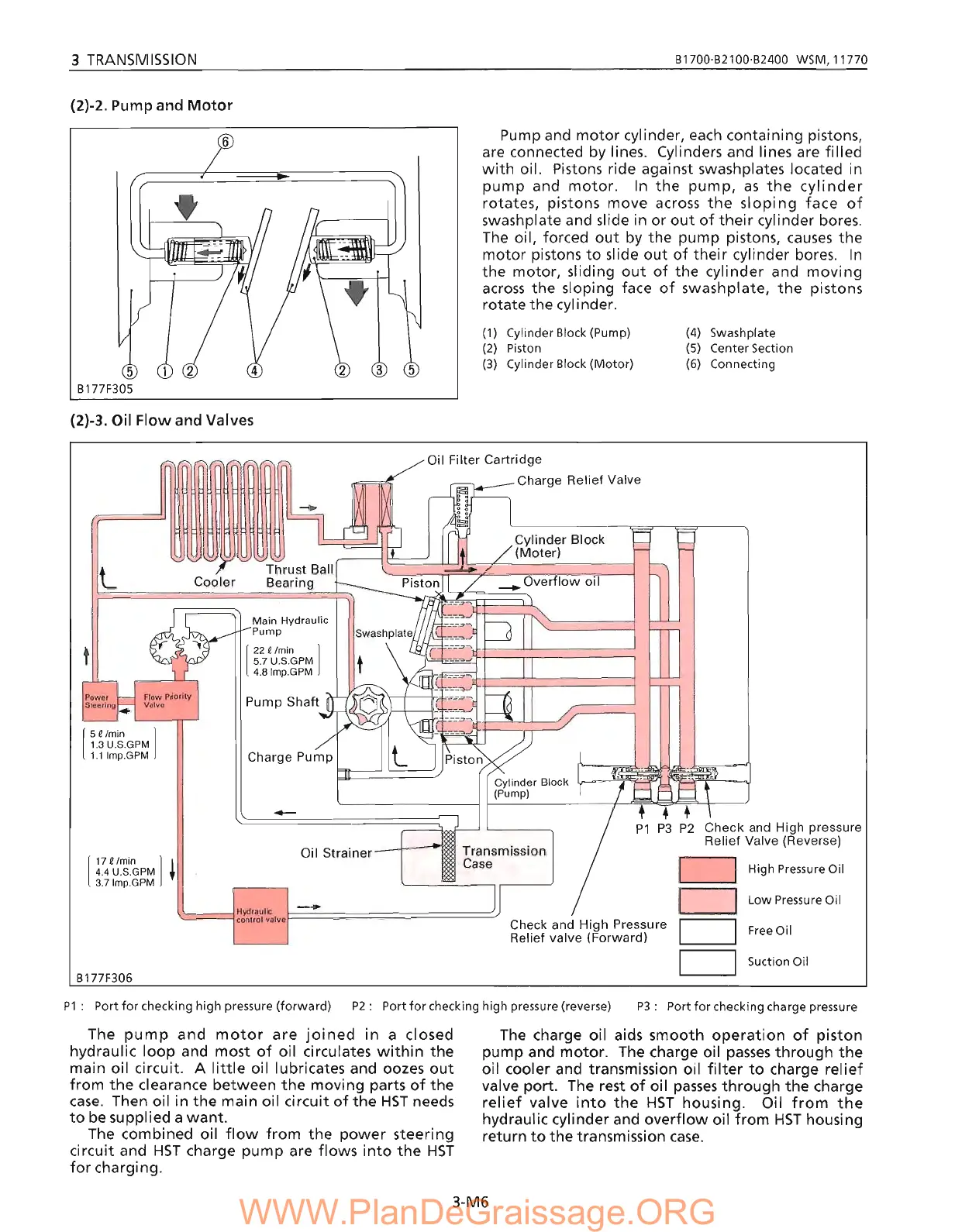
Pump and
motor
cylinder, each containing pistons,
are connected by lines. Cylinders and lines are filled
with
oil. Pistons ride against swashplates located in
pump
and
motor.
In
the
pump,
as
the
cylinder
rotates, pistons move across
the
sl
opi
ng face
of
swashplate and slide in
or
out
of
their
cylinder bores.
The
oil, forced
out
by the pump pistons,
causes
the
motor
pistons
to
slide
out
of
their
cylinder bores.
In
the motor, sliding
out
of
the cylinder and
moving
across
the sloping face
of
swashplate,
the
pistons
rotate
the
cylinder.
6
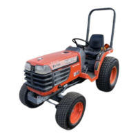
(2)-3. Oil
Flow
and Valves
(1)
Cylinder
810ck
(Pump)
(2)
Piston
(3)
Cylinder
810ck
(Motor)
(4)
Swash
plate
(5)
Center Section
(6)
Connecting
L
[
5
€Imin ]
1.3 U.S.GPM
1.1Imp.GPM
[
17
€Imin ] I
4.4 U.S.GPM t
3.7Imp.GPM
8177F306
Cooler
Thrust
Ball
Bearing
Main
Hydraulic
Pump
[
22
€Imin ]
5.7
U.S.GPM
4.8Imp.GPM
-
Oil
Strainer
Oil Filter
Cartridge
r=,-,
Charge
Relief
Valve
Cylinder
Block
(Pump)
Transmission
Case
Check and
High
Pressure
Relief
valve
(Forward)
Check
and High pressure
Relief Valve (Reverse)
High Pressure Oil
Low
Pressure
Oil
Free
Oil
Suction Oil
P1: Port
for
checking high pressure (forward) P2: Port
for
checking high pressure (reverse)
P3: Port
for
checking charge pressure
The
pump
and
motor
are
joined
in
a closed
hydraulic
loop
and most
of
oil circulates
within
the
main oil circuit. A
little
oil lubricates and oozes
out
from
the
clearance between
the
moving parts
of
the
case.
Then oil in
the
main oil circuit
of
the
HST
needs
to
be
supplied a
want.
The combined oil
flow
from
the
power
steering
circuit and
HST
charge pump are flows
into
the
HST
for
charging.
The charge oil aids smooth
operation
of
piston
pump and motor. The charge oil
passes
through
the
.oil cooler and transmission oil
filter
to
charge
relief
valve port. The rest
of
oil
passes
through
the
charge
relief
valve
into
the
HST
housing. Oil
from
the
hydraulic cylinder and
overflow
oil
from
HST
housing
return
to
the
transmission
case.
3-M6