1
ENGINE
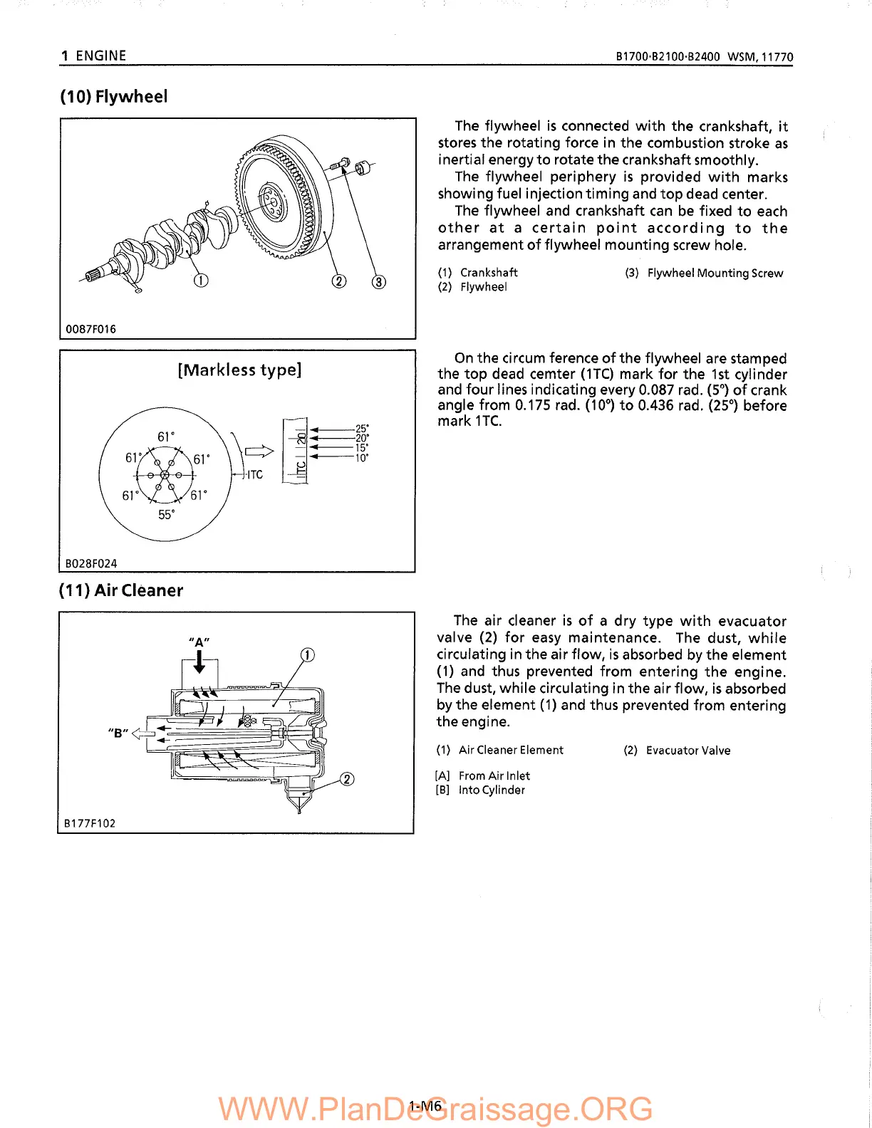
(10) Flywheel
B1700·B21 00·B2400 WSM, 11770
The
flywheel
is
connected
with
the crankshaft,
it
stores the rotating force in the combustion stroke
as
inertial energy
to
rotate the crankshaft smoothly.
The
flywheel periphery
is
provided
with
marks
showing fuel injection timing and
top
dead center.
The
flywheel
and
crankshaft
can
be
fixed
to
each
other
at
a
certain
point
according
to
the
arrangement
of
flywheel mounting screw hole.
0087F016
(1) Crankshaft
(2) Flywheel
(3) Flywheel
Mounting
Screw
[Markless
type]
61'
61~61'
61~1'
55'
B028F024
(11) Air Cleaner
I
]"'
25"
---fl
"'
20"
.....--->---..
--15"
'-----,/
-
of
1
0"
<.)
-ITe
~
On
the circum ference
ofthe
flywheel are stamped
the
top
dead cemter
(He)
mark
for
the
1st
cylinder
and
four lines indicating every 0.087 rad.
(5°)
of
crank
angle from
0.175
rad.
(10°)
to
0.436 rad.
(25°)
before
mark
1TC.
The
air cleaner
is
of
a dry type
with
evacuator
valve
(2)
for
easy
maintenance.
The
dust,
while
circulating in the air flow,
is
absorbed
by
the element
(1)
and
thus prevented from entering
the
engine.
The
dust, while circulating in the air flow,
is
absorbed
by
the element
(1)
and thus prevented from entering
the engine.
IIA"
B177F102
(1)
AirCleanerElement
[A] From
Air
Inlet
[B]
Into
Cylinder
1-M6
(2) Evacuator Valve

 Loading...