2
CLUTCH
81700·82100·82400 WSM,11770
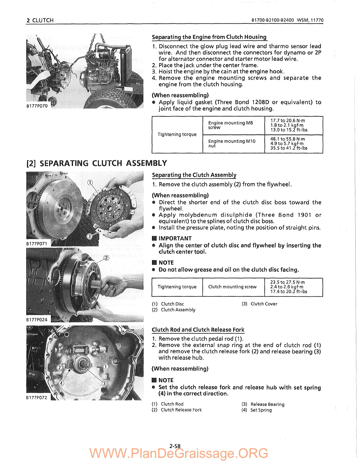
separating the Engine from Clutch Housing
1.
Disconnect the
glow
plug lead wire and tharmo sensor lead
wire. And then disconnect the connectors
for
dynamo
or
2P
for
alternator connector and starter
motor
lead wire.
2.
Place
the jack under the center frame.
3. Hoist the engine
by
the cain at the engine hook.
4.
Remove
the
engine
mounting
screws and separate
the
engine from the clutch housing.
(When reassembling)
.. Apply liquid gasket (Three Bond 1208D
or
equivalent)
to
joint
face
of
the engine and clutch housing.
Engine mounting M8
17.7
to
20.6 N'm
1.8
to
2.1
kgf'm
screw
13.0
to
15.2 ft-Ibs
Tightening torque
Engine mounting M10
48.1
to
55.8 N'm
4.9
to
5.7
kgf'm
nut
35.5
to
41.2 ft-Ibs
_
NOTE
• Do
not
allow
grease and oil on the clutch disc facing.
23.5
to
27.5 N'm
Tightening
torque
Clutch mounting screw
2.4
to
2.8
kgf'm
17.4
to
20.2 ft-Ibs
Clutch
Rod
and Clutch
Release
Fork
1.
Remove
the clutch pedal rod
(1).
2.
Remove
the external
snap
ring at the end
of
clutch rod
(1)
and remove the clutch release
fork
(2)
and release bearing (3)
with
release hub.
(When reassembling)
_
NOTE
•
Set
the clutch release
fork
and release hub
with
set spring
(4) in the correct direction.
(3)
Clutch Cover
(1) Clutch
Disc
(2)
Clutch Assembly
[2] SEPARATING CLUTCH ASSEMBLY
separating the Clutch Assembly
1.
Remove
the clutch assembly
(2)
from the flywheel.
(When reassembling)
.. Direct the shorter end
of
the clutch disc
boss
toward
the
flywheel.
•
Apply
molybdenum
disulphide
(Three
Bond
1901
or
equivalent)
to
the splines
of
clutch
disc
boss
.
.. Install the pressure plate, noting the position
of
straight pins.
_IMPORTANT
• Align the center
of
clutch disc and flywheel by inserting the
clutch center tool.
(1) Clutch
Rod
(2)
Clutch
Release
Fork
(3)
Release
8earing
(4)
Set
Spring
2-58

 Loading...