ASSEMBLY
OM 0361BR-AC 14
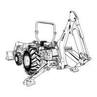
8. Figure 7: Raise the broom with the
tractor's lift mechanism. Remove the 1/4"
wire lock pin (item 1). Raise the parking
stand (item 2) and reinstall the 1/4" wire
lock pin (item 1) as illustrated on the figure.
Repeat the same procedure for the second
parking stand.
Installation of the Support Chain
(Figures 8-9-10)
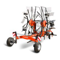
1. Figure 8: Remove the bolt (item 1A) from
each clevis (item 1).
2. Figure 8: Insert a clevis (item 1) at each
end of the chain (item 2)
3. Figure 8: Attach the retaining plate
(item 3) to one clevis (item 1) with the bolt
(item 1A).
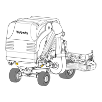
4. Figure 9: Attach the other clevis (item 1) in
one of the holes of the perforated plate of
the female hitch (item 2) with the bolt
(fig. 8, item 1A).
5. Figure 9: Attach one of the holes of the
retaining plate (item 3) to the subframe pin
(item 4) with the hairpin (item 5).
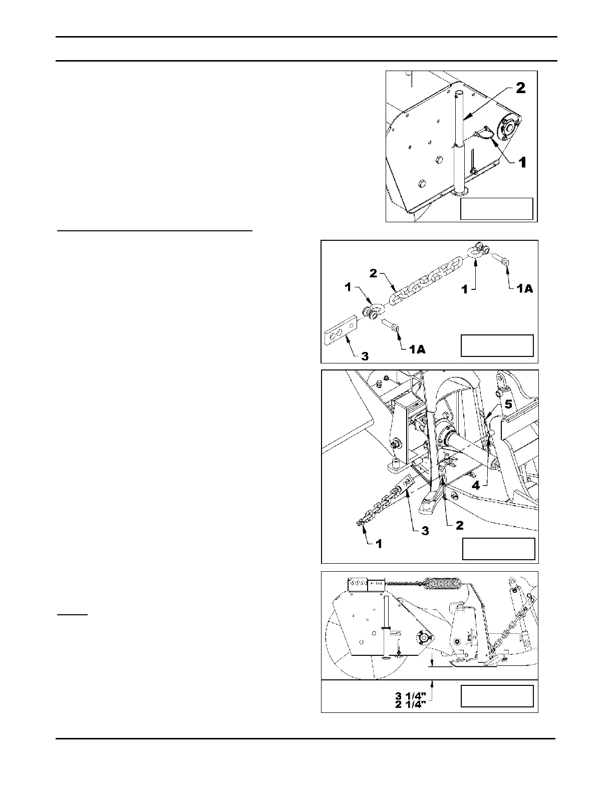
6. Figure 10: Lower the broom until the chain
is fully extended. Measure the distance
between the bottom of the male hitch nose
and the ground. The distance should be
between 2 1/4" and 3 1/4". If it's not within
that range, attach the chain in another hole
of the perforated plate (fig. 9, item 2)
and/or, attach the other hole of the
retaining plate (fig. 9, item 3). Continue
doing this until you reach the correct
distance.
NOTE
: Before using the broom, perform all
the adjustments listed in the section
"Operation".
Figure 7
Figure 8
Figure 9
Figure 10
 Loading...