2-M1
GL6000, GL7000, GL9000, GL11000, WSM
GENERATOR
1. STRUCTURE
1. Stator Assembly
The main coil and sub coil for power generation are
wound in the slots provided in the core.
The main coil generates the AC output and supplies
A.V.R. assembly with a sensing voltage.
The sub coil, working as an excitation coil, supplies
the field current to the rotor through A.V.R. assembly.
2. Rotor Assembly
The coils are wound to magnetize the entire core.
3. Brush Holder Assembly
The excitation voltage from sub coil of the stator
assembly is applied to the rotor coil through the A.V.R.
assembly rectifying circuit and the brush holder
assembly.
4. Automatic Voltage Regulator (A.V.R.) Assembly
The A.V.R. assembly maintains the AC output voltage
at a constant level.
W1015204
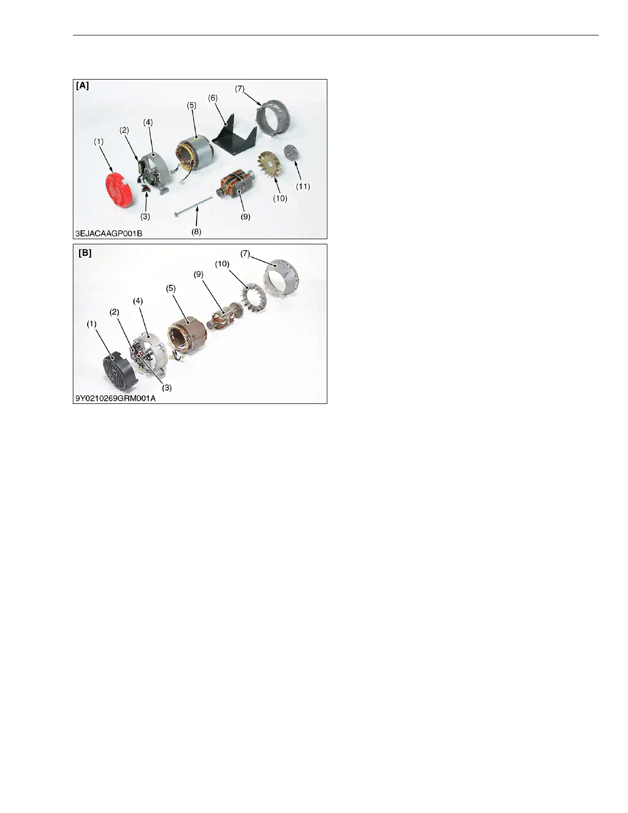
(1) Rear Cover
(2) A.V.R. Assembly
(3) Brush Holder Assembly
(4) Rear Bracket
(5) Stator Assembly
(6) Generator Plate
(7) Stator Housing
(8) Center Bolt
(9) Rotor Assembly
(10) Fan
(11) PTO Shaft
[A] GL6000, GL7000
[B] GL9000, GL11000
 Loading...