Home
Kubota
Portable Generator
GL6000
Kubota GL6000 User Manual
4
of 1
of 1 rating
154 pages
Give review
Manual
Specs
To Next Page
To Next Page
To Previous Page
To Previous Page
Loading...
G-3
GL6000, GL7000, GL9000, GL11000, WSM
G
GENERAL
[3]
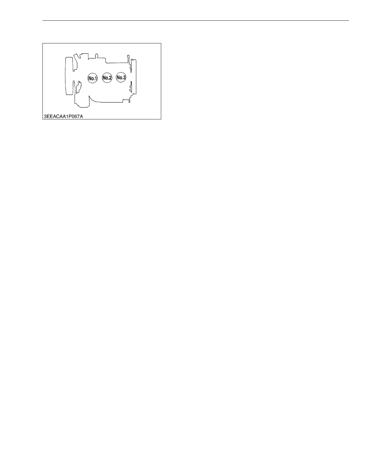
CYLINDER NUMBER
The cylinder numbers of KUBOTA
diese
l engine are designated
as shown
in the figu
re.
The sequence
of cylinder num
bers is given as
No.1, No.2 an
d
No.3 starting fro
m the gear case si
de.
W1011077
KiSC issued 05, 2015 A
16
18
Table of Contents
General
14
Default Chapter
4
Safety First
4
Specifications
9
Table of Contents
14
1 Identification
15
Model Name and Engine Serial Number
15
E4B Engine
16
Cylinder Number
17
2 Precaution
18
3 Handling Precautions for Electrical Parts and Wiring
19
Wiring
19
Battery
21
Fuse
21
Connector
21
Handling of Circuit Tester
22
4 Lubricants, Fuel and Coolant
23
5 Tightening Torques
25
General Use Screws, Bolt and Nuts
25
Stud Bolts
25
6 Maintenance Check List
26
7 Check and Maintenance
28
Daily Check
28
Check Points of Initial 50 Hours
29
Check Point of Every 50 Hours
30
Check Point of Every 100 Hours
30
Check Point of Every 200 Hours
32
Check Point of Every 300 Hours
33
Check Point of Every 400 Hours
33
Check Points of Every 500 Hours
34
Check Point of Every 800 Hours
36
Check Point of Every 1000 Hours
37
Check Point of Every 1500 Hours
37
Check Point of Every 1 Year
38
Check Point of Every 2 Years
38
8 Special Tools
40
Mechanism
45
Engine Body
46
Half-Floating Head Cover
46
Lubricating System
47
Cooling System
48
Fuel System
49
Servicing
50
1 Troubleshooting
51
2 Servicing Specifications
54
3 Tightening Torques
60
Tightening Torques for Special Use Screws, Bolt and Nuts
60
Tightening Torques for General Use Screws, Bolts and Nuts
61
4 Checking, Disassembling and Servicing
62
Checking and Adjusting
62
Engine Body
62
Lubricating System
65
Cooling System
66
Fuel System
68
Electrical System
71
Preparation
75
Separating Engine
75
Disassembling and Assembling
78
Cylinder Head and Valves
78
Timing Gears, Camshaft, Fuel Camshaft and Oil Pan
82
Piston and Connecting Rod
86
Crankshaft
88
Water Pump
90
Injection Nozzle
90
Starter
91
Servicing
93
Cylinder Head and Valves
93
Timing Gears, Camshaft and Fuel Camshaft
98
Piston and Connecting Rod
101
Crankshaft
103
Cylinder
107
Oil Pump
108
Starter
109
Mechanism
112
Structure
113
Automatic Voltage Regulator (A.V.r.)
114
Emergency Relay Circuit
117
General
117
Instructions
118
Earth
119
Wiring Diagram
120
Servicing
131
1 Troubleshooting
132
Generator
132
Engine Circuit
135
2 Servicing Specifications
137
3 Tightening Torques
139
Tightening Torques for Special Use Screws, Bolts and Nut
139
Tightening Torques for General Use Screws, Bolts and Nut
140
4 Checking, Disassembling and Servicing
141
Checking and Adjusting
141
Control Panel
141
Emergency Relay Activates
147
Disassembling and Assembling
148
External Components
148
Servicing
151
Terminal Voltage for each Part During Normal Periods (No-Load Periods)
151
Stator Coil
151
Rotor Coil
152
Exciter Coil
153
4
Based on 1 rating
Ask a question
Give review
Questions and Answers:
Need help?
Do you have a question about the Kubota GL6000 and is the answer not in the manual?
Ask a question
Kubota GL6000 Specifications
General
Brand
Kubota
Model
GL6000
Category
Portable Generator
Language
English
Related product manuals
Kubota GL6000-STD
62 pages
Kubota GL6000-AUS
62 pages
Kubota GL6000A-AU-B
171 pages
Kubota GL6000D-AU-B
171 pages
Kubota GL9000
154 pages
Kubota GL7000
154 pages
Kubota GL11000
154 pages
Kubota GL7000-USA
62 pages
Kubota GL9000-STD
62 pages
Kubota GL9000-AUS
62 pages
Kubota GL11000-USA
62 pages
Kubota GL11000-USA-TM
62 pages
 Loading...