1-S37
GL6000, GL7000, GL9000, GL11000, WSM
ENGINE
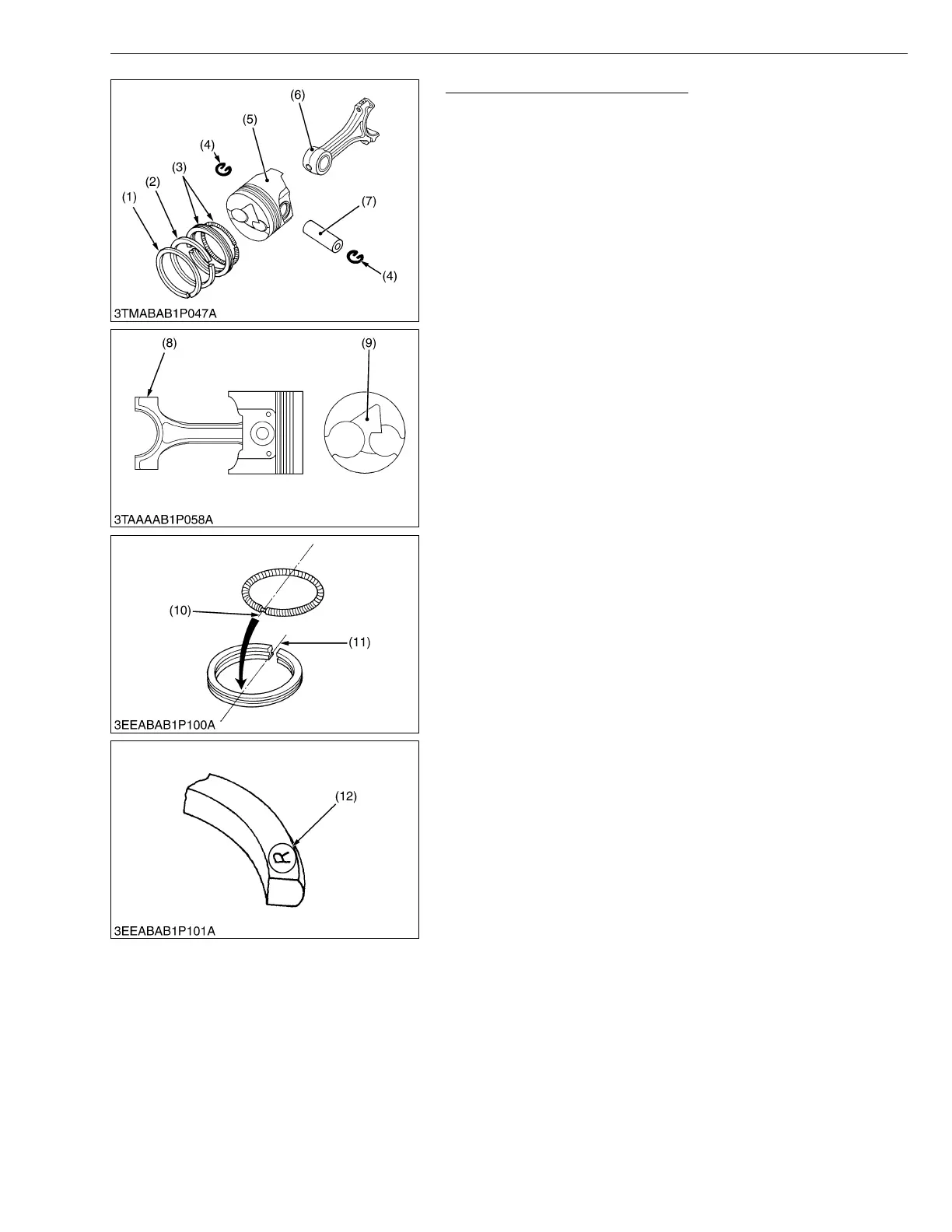
Piston Ring and Connecting Rod
1. Remove the piston rings using a piston ring tool.
2. Remove the piston pin (7), and separate the connecting rod (6)
from the piston (5).
(When reassembling)
• When installing the ring, assemble the rings so that the
manufacturer’s mark (12) near the gap faces the top of the piston.
• When installing the oil ring onto the piston, place the expander
joint (10) on the opposite side of the oil ring gap (11).
• Apply engine oil to the piston pin.
• When installing the connecting rod to the piston, immerse the
piston in 80 C (176 °F) oil for 10 to 15 minutes and insert the
piston pin to the piston.
• When installing the connecting rod to the piston, align the mark
(8) on the connecting rod to the fan-shaped concave (9).
• Mark the same number on the connecting rod and the piston
so as not to change the combination.
W10281670
(1) Top Ring
(2) Second Ring
(3) Oil Ring
(4) Piston Pin Snap Ring
(5) Piston
(6) Connecting Rod
(7) Piston Pin
(8) Mark
(9) Fan-Shaped Concave
(10) Expander Joint
(11) Oil Ring Gap
(12) Manufacturer’s Mark
 Loading...