ASSEMBLY
OM 0297SB-AU
11
Figure 1
SNOWBLOWER ASSEMBLY
The snowblower is pre assembled at the factory, however, parts in the bag and box must be
assembled. Use the present manual and lay out all parts for assembly. Separate bolts and nuts into
various sizes. After assembly, torque all the bolts according to the "Torque Specification Table"
enclosed at the end of the manual.
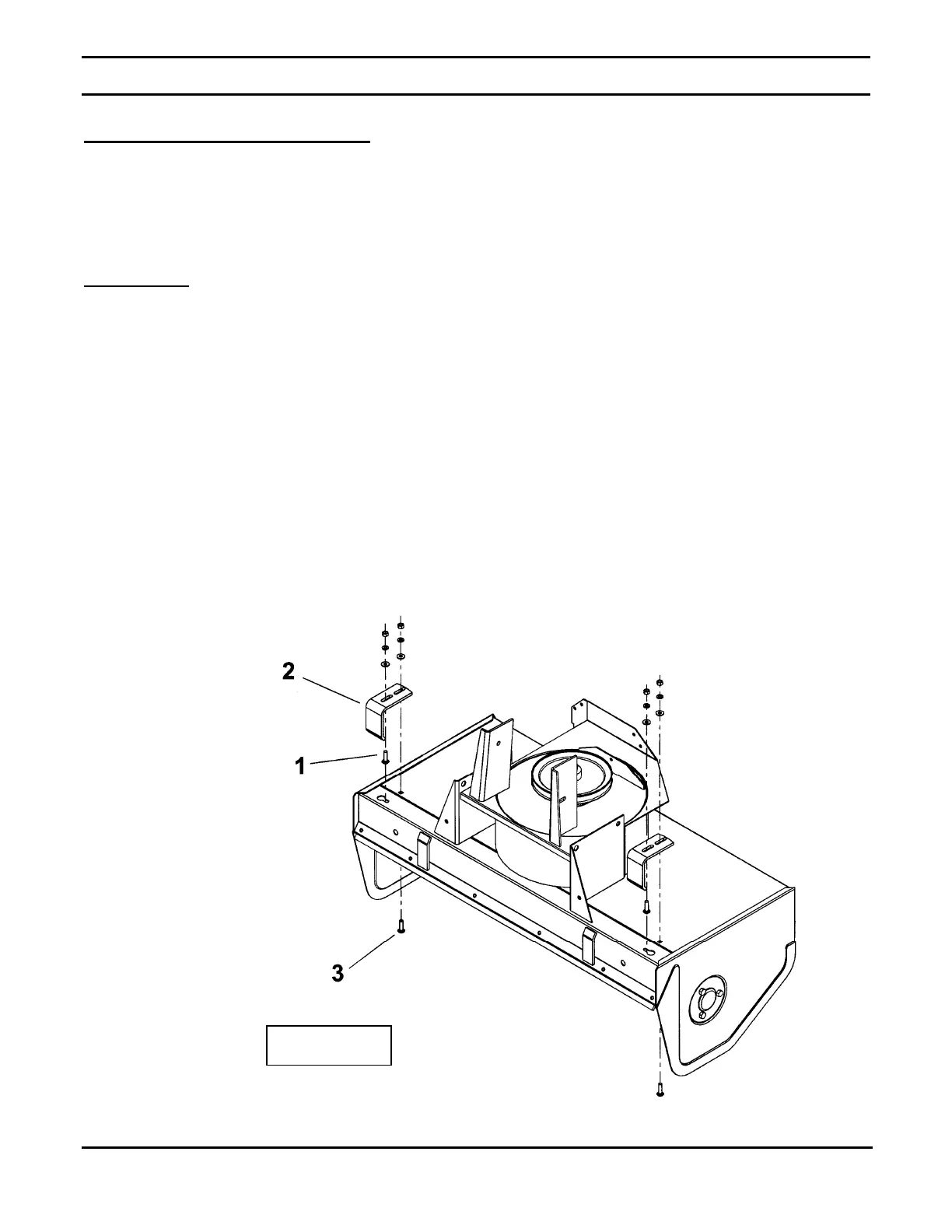
Skid Shoes (Figure 1)
For skid shoe assembly, place the snowblower
on a flat and level surface with the auger facing
down.
1. From inside the bend of each skid shoe (item
2), insert a 5/16" NC x 1" carriage bolt (item
1) through the lower slotted hole. Loosely
install a 3/8" dia. hole flatwasher, 5/16"
lockwasher and 5/16" NC hex. nut on each
bolt.
2. Insert bolt (item 1) heads of each skid shoe
in the round portion of the "keyholes", on
each side of snowblower body.
3. Slide the square shank portion of bolt heads
all the way into the slots.
4. Insert the two remaining 5/16" NC x 1"
carriage bolts (item 3) in the square holes
located on each side of snowblower body
and secure with a 3/8" dia. hole flatwasher, a
5/16" lockwasher and a 5/16" NC nut.
5. Tighten all bolts securely.
IMPORTANT : Clearance between cutting
edge and surface:
Level paved surface : Adjust to 1/16" to 1/8"
Uneven or gravel surface: Adjust to 1/2" to 5/8"
 Loading...